SHARE Knowledge Hub
Isolation, Lockout and Line Breaking
Isolation, lockout and line-breaking prevent stored energy or hazardous material reaching people when plant is opened for work. A lock or permit alone cannot prove the correct line is dead, depressurised, drained and safe to break. The isolation plan must identify every connected source, use an appropriate physical standard, verify zero-energy conditions at the point of work, control the break and formally hand the plant back before restart.
Understanding Isolation, Lockout and Line Breaking
Isolation, lockout and line-breaking prevent stored energy or hazardous material reaching people when plant is opened for work. A lock or permit alone cannot prove the correct line is dead, depressurised, drained and safe to break. The isolation plan must identify every connected source, use an appropriate physical standard, verify zero-energy conditions at the point of work, control the break and formally hand the plant back before restart.
Why this matters at work
Line-breaking can expose workers to hazardous substances even without a large process-safety event. COSHH assessment should cover residual chemicals, mist, dust, cleaning agents and by-products; skin and eye routes matter alongside inhalation. Steam can scald, cryogenic liquid can cause cold injury and oxygen displacement, and pressurised fluid can penetrate skin. A release may also cause panic, falls or secondary injuries.
Where repeated exposure may occur, assess whether exposure monitoring or health surveillance is required under the applicable COSHH duty. A lack of reported illness does not establish that containment is effective. Correct failed controls and examine similarly exposed groups without disclosing confidential clinical information in the permit record.
How organisations manage this in practice
Evidence of fulfilment includes current drawings reconciled to plant, approved isolation standards, a task-specific method, competent authorised roles, isolation and zero-energy tests, inspection and lock control, emergency arrangements, contractor coordination and management review of deviations. A site should be able to explain why a lower standard was accepted and who independently approved it. Do not infer that a permit alone satisfies any of these duties.
Use an isolation method designed and applied by a competent electrical person. Secure each source, prove dead at the work location with suitable test equipment, verify the tester before and after, and manage stored charge or earthing under the system rules. Where re-energisation for testing is required, end the exposed work phase, clear people and tools, reinstate guards or barriers, and issue a separate controlled test stage. Do not casually "try it live" while another worker remains on the machine.
Competent people should establish the safe state and prove the relevant isolation and support before access. Record the boundary, locks, restraints, work limits and verification. Ensure nobody removes support or restores energy while others remain exposed, including at shift change. Use manufacturer instructions and task-specific assessment for the actual machine; do not improvise supports from this example. HSE maintenance guidance requires safe planning and prevention of unexpected movement, with the final technical method determined by the equipment and hazards.
What must happen before intrusive work starts?
No intrusive work should start until the correct system is identified, isolated, locked, depressurised, drained, vented, tested and authorised.
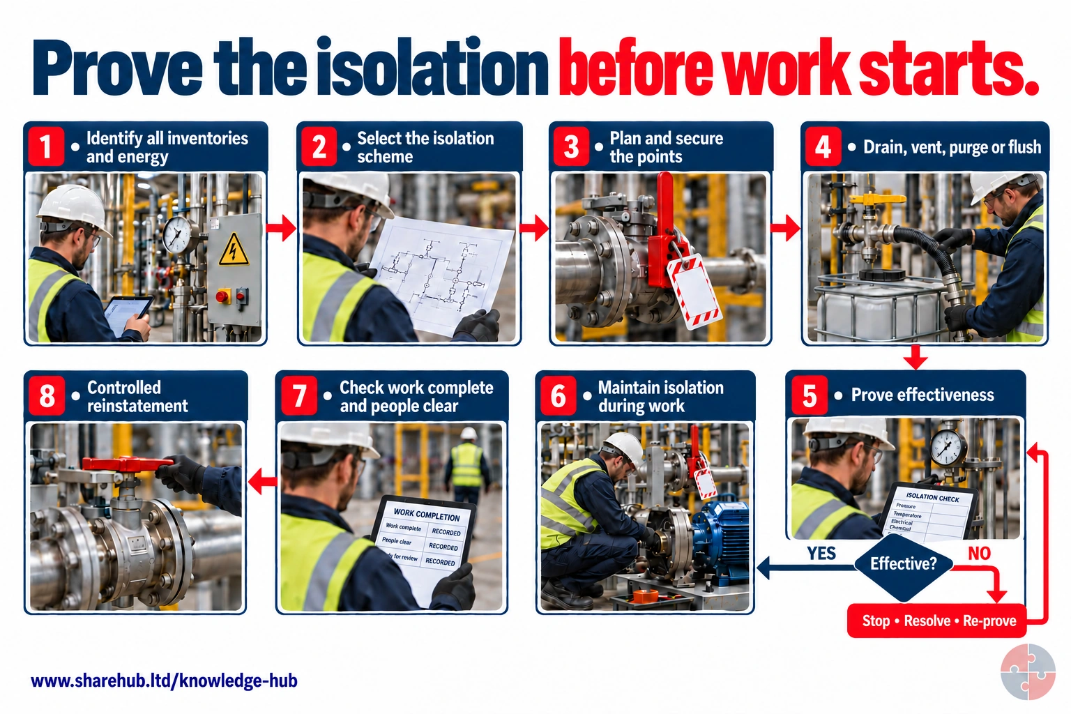
Identify all relevant inventories and energy, assess and select an isolation scheme, prepare and secure the isolation, remove hazardous inventory as required and prove effectiveness before intrusive work. Keep the isolation effective throughout work, confirm completion and people clear, then reinstate under control. The secured quarter-turn valves are shown transverse to their pipes during work.
Why does an isolation need monitoring after it has been proved?
Conditions or isolation integrity can change. The controls must remain effective throughout the intrusive activity and until controlled reinstatement.
High-level process-isolation framework, not an isolation scheme, permit or instruction to break containment. A closed-looking handle or zero gauge reading alone does not prove isolation; specify and verify the actual isolation points and trapped-energy controls.
Source guidance: HSE HSG253
Best-practice guide: Isolation, Lockout and Line Breaking
What must happen before intrusive work starts?
No intrusive work should start until the correct system is identified, isolated, locked, depressurised, drained, vented, tested and authorised. Isolation, lockout and line-breaking prevent stored energy or hazardous material reaching people when plant is opened for work.
Turn isolation, lockout and line breaking knowledge into a decision
Isolation, lockout and line-breaking prevent stored energy or hazardous material reaching people when plant is opened for work. A lock or permit alone cannot prove the correct line is dead, depressurised, drained and safe to break. Keep marked drawings, isolation certificate, independent check, locks, drain/test results, permit, SIMOPS coordination, first-break record and handback.
Opening a hydrocarbon pump discharge line
Open the target gasket flange under controlled conditions with containment, ignition control, atmosphere test where needed and a defined escape route. After work, inspect the spool, remove blinds and locks only through authorised sequence, pressure-test where required, update the permit and hand back to operations before restart.
Where do isolation and line-breaking systems commonly fail?
Common failures are usually predictable and should be designed out or caught by assurance.
Choose controls for isolation, lockout and line breaking
Elimination: Use a suitable external diagnostic or redesigned sampling arrangement if it removes the intrusive valve task. Engineering controls: Use an approved closed sampling system or safely removable module to reduce open access. Engineering controls: Isolate connected feeds and energy sources, remove hazardous contents and verify the defined safe state before breaking containment. Engineering controls: Provide suitable drainage, containment, local extraction and support for the valve and connected pipework. Administrative controls: Agree the permit, contamination checks, line identification and hand-back with operations and contractors. Read the full control table for qualifications, ownership and verification. Use the actual task and applicable jurisdiction; existing technical approval remains unchanged.
Use the full isolation, lockout and line breaking lesson
Use the full topic for the decision points, practical examples, detailed control tables and source scope. HSE guidance applies to Great Britain; use HSENI for the Northern Ireland route and the source’s stated jurisdiction. A simplified guide does not change the page’s technical-review or approval status.

Read all six steps as text
1. What must happen before intrusive work starts?
No intrusive work should start until the correct system is identified, isolated, locked, depressurised, drained, vented, tested and authorised.
- Avoid / redesign: Use a suitable external diagnostic or redesigned sampling arrangement if it removes the intrusive valve task.
- Control the task: Isolate connected feeds and energy sources, remove hazardous contents and verify the defined safe state before breaking containment.
- Verify before release: If the hazardous step remains, keep it within the task assessment and select the stronger feasible remaining controls.
No intrusive work should start until the correct system is identified, isolated, locked, depressurised, drained, vented, tested and authorised. Isolation, lockout and line-breaking prevent stored energy or hazardous material reaching people when plant is opened for work.
Apply it: Which part of this plan would you check at the workface before authorising the task?
2. Turn isolation, lockout and line breaking knowledge into a decision
Use the evidence to improve the actual work arrangement.
- Change at source: Use a suitable external diagnostic or redesigned sampling arrangement if it removes the intrusive valve task.
- Make it observable: If the hazardous step remains, keep it within the task assessment and select the stronger feasible remaining controls.
- Keep useful evidence: Keep marked drawings, isolation certificate, independent check, locks, drain/test results, permit, SIMOPS coordination, first-break record and handback.
Isolation, lockout and line-breaking prevent stored energy or hazardous material reaching people when plant is opened for work. A lock or permit alone cannot prove the correct line is dead, depressurised, drained and safe to break. Keep marked drawings, isolation certificate, independent check, locks, drain/test results, permit, SIMOPS coordination, first-break record and handback.
Apply it: What evidence would show that the change improves this task, rather than only completing a record?
3. Opening a hydrocarbon pump discharge line
Example: a practical application of the existing topic lesson.
- Setting: Maintenance must remove a pump spool in a fuel terminal.
- Act: Establish and prove initial isolation; then safely depressurise, drain and purge the section.
- Hold / review: Stop if pressure returns, the line identity is uncertain, isolation leaks, the drain path is blocked or the adjacent team changes the system.
Open the target gasket flange under controlled conditions with containment, ignition control, atmosphere test where needed and a defined escape route. After work, inspect the spool, remove blinds and locks only through authorised sequence, pressure-test where required, update the permit and hand back to operations before restart.
Apply it: At which point would you hold this example, and what evidence would allow it to proceed?
4. Where do isolation and line-breaking systems commonly fail?
Connect the task, the route to the person and the control that can fail.
- Source / exposure: Common failures are usually predictable and should be designed out or caught by assurance.
- Possible consequence: Wrong line identity, passing valves, back-feed, blocked drains and incomplete handback can each defeat a signed plan.
- Control failure: Treat these as testable failure modes with named checks, not as reminders to be careful.
Common failures are usually predictable and should be designed out or caught by assurance.
Apply it: Who could be exposed, including other trades, cleaners, maintainers and people nearby?
5. Choose controls for isolation, lockout and line breaking
Start with the stronger practicable options and verify their effect.
- Elimination: Use a suitable external diagnostic or redesigned sampling arrangement if it removes the intrusive valve task.
- Engineering controls: Use an approved closed sampling system or safely removable module to reduce open access.
- Engineering controls: Isolate connected feeds and energy sources, remove hazardous contents and verify the defined safe state before breaking containment.
- Engineering controls: Provide suitable drainage, containment, local extraction and support for the valve and connected pipework.
- Administrative controls: Agree the permit, contamination checks, line identification and hand-back with operations and contractors.
Elimination: Use a suitable external diagnostic or redesigned sampling arrangement if it removes the intrusive valve task. Engineering controls: Use an approved closed sampling system or safely removable module to reduce open access. Engineering controls: Isolate connected feeds and energy sources, remove hazardous contents and verify the defined safe state before breaking containment. Engineering controls: Provide suitable drainage, containment, local extraction and support for the valve and connected pipework. Administrative controls: Agree the permit, contamination checks, line identification and hand-back with operations and contractors. Read the full control table for qualifications, ownership and verification. Use the actual task and applicable jurisdiction; existing technical approval remains unchanged.
Apply it: Which stronger option can be used here, and who will verify it before accepting the remaining risk?
6. Use the full isolation, lockout and line breaking lesson
Follow the official sources below and retain the task-specific evidence.
- Official guidance: HSG253 - The safe isolation of plant and equipment
- Official guidance: HSG250 - Guidance on permit-to-work systems
- Task decision: Keep marked drawings, isolation certificate, independent check, locks, drain/test results, permit, SIMOPS coordination, first-break record and handback.
Use the full topic for the decision points, practical examples, detailed control tables and source scope. HSE guidance applies to Great Britain; use HSENI for the Northern Ireland route and the source’s stated jurisdiction. A simplified guide does not change the page’s technical-review or approval status.
Apply it: Which official source and full-topic section will you use to resolve the next decision?
If there is any doubt about the plant identity, isolation boundary, stored energy, pressure, hazardous contents, electrical feed, back-feed, valve integrity, drain/vent path or rescue arrangements, the job should pause. Guessing is not a control. See HSG253 - The safe isolation of plant and equipment.
Line breaking and isolation are not paperwork exercises. They physically decide whether a worker is protected from live electricity, rotating equipment, pressure, steam, toxic gas, flammable vapour, corrosive liquid, hot material, hydraulic movement or product release.
- Correct equipment identified — Wrong isolation creates false safety. Tags, drawings or physical plant do not match.
- All energy sources identified — Hidden feeds or stored energy can harm workers. UPS, hydraulic, pneumatic, gravity or back-feed not addressed.
- Isolation applied and locked — Prevents operation or re-energisation. Lock missing, shared key unclear or tag only.
- Pressure/contents removed — Prevents release during line breaking. Gauge, vent, drain or sample evidence unclear.
- Isolation verified — Confirms the worksite is safe. No test, no prove-dead, no bleed/drain confirmation.
- Permit and certificate match — Work scope must align with isolation scope. Permit describes different plant, task or boundary.
What are the key facts about isolation and line breaking?
The key fact is that a locked isolation is only safe if the right energy has been identified and verified.
A closed valve can leak, an electrical circuit can be back-fed, and a low point can hold hazardous liquid after a drain appears empty. The permit and isolation certificate serve different purposes: one authorises the work, the other records the specified isolation and its verification evidence. Independent verification, named locks, point-of-work testing and controlled reinstatement are essential where failure could release pressure, toxic material or ignition energy. See HSG253 - The safe isolation of plant and equipment.
Switching off is not enough
Isolation must prevent unexpected start-up and control stored energy.
Line breaking is intrusive
Opening containment can release pressure, product, toxic material or flammable atmosphere.
Verification is a barrier
Isolation must be proved, not assumed from drawings or valve labels alone.
Isolation and permits are linked
The permit authorises work; the isolation certificate records the specified isolation and verification evidence.
Handback is safety-critical
Reinstatement, leak testing and removal of locks need the same discipline as isolation.
How can I practise this topic in 3D?

A fan repair starts without a handover
A blocked-in liquid section has no reviewed expansion route

Dosing equipment is changed without safe isolation
All related inspection points 18 across 7 locations
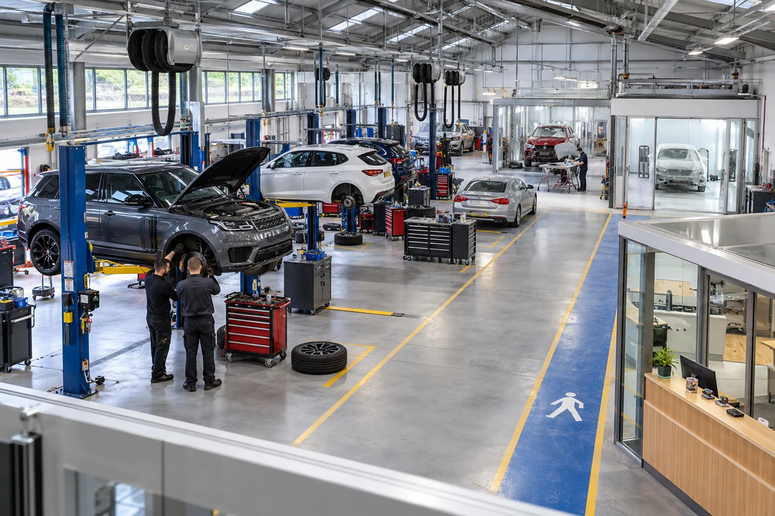
Garage workshop 2 inspection points
Crown Fuels terminal 4 inspection points
Riverside Leisure 1 inspection point
Harvest & winter housing 6 inspection points
From flour to chilled despatch 1 inspection point
A safer place to call home 1 inspection point
Recover materials. Protect people. 3 inspection points
Practice in the SHAREhub environment. Browser practice is separate from workplace competence and formal learning records.
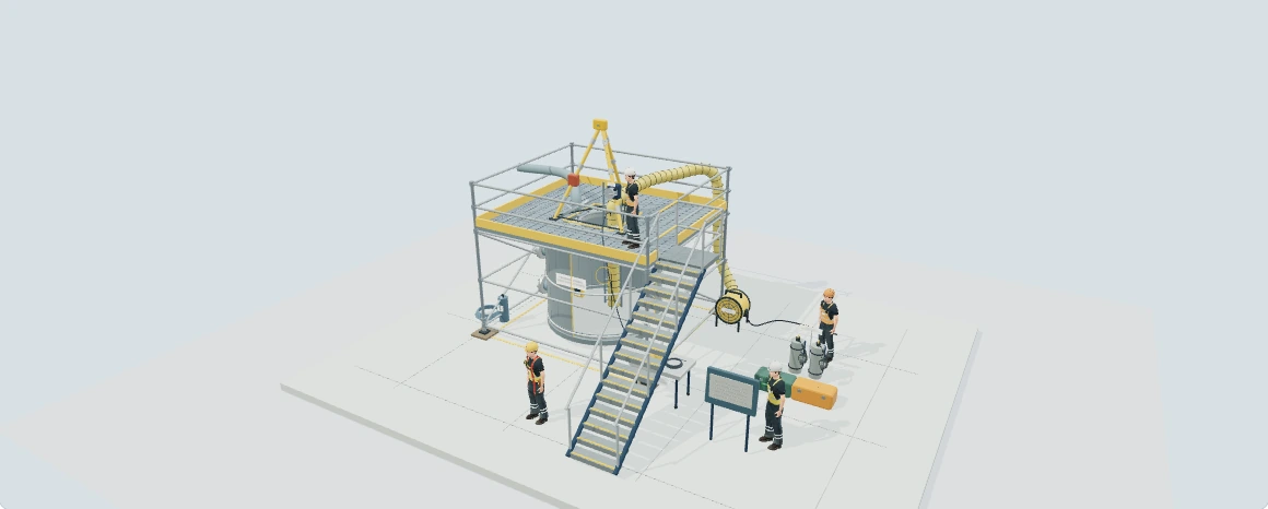
Explore petrol-tank isolation in 3D
Follow the fill and suction lines, inspect valve internals and compare retained liquid and vapour in a fictional petrol-tank system. The separate 22-stage preparation, external maintenance and handback example now sits alongside the four task reviews and eight original learning stops.
Included with Paid membership. Authorised staff can review the model. Free members can use the eight illustrated isolation arrangements on this page.
Preparation, work and return to service: The 22-stage example follows initial isolation and inventory recovery; temporary water and collection hoses at the DBB bleed connections; nitrogen to a reviewed top vent; pressure and gas-test evidence; locks and example documents; the protected first break and final spades; external pump work; then protected spade removal, remade joints, specified bolting and a separate line-test and handback review. Select Start guided example to follow the authored scenes. Stop restores the saved manual example; browsing the stage text alone leaves it unchanged.
Know the difference: positive isolation uses physical separation or a suitable solid barrier. Proved valved isolation has accepted test evidence for the required barriers. Unproved (unproven) valved isolation lacks that evidence; closed handles or a quiet bleed do not establish proof.
Choose a task: instrument calibration; pump and motor maintenance; spade or spectacle-blind work; or a confined-space entry review. Inspect double block and bleed on the fill and suction lines, the wider boundary, electrical energy and temporary services.
Eight steps: read the system; match the task; inspect valve closure; challenge the evidence; review the first break; consider cleaning; examine nitrogen hazards; then review work and handback holds. Water flushing does not prove gas-free conditions, and nitrogen can create a fatal oxygen-deficient atmosphere.
Temporary connections: attach the illustrative water or nitrogen supply at the inlet DBB bleed. The water return uses the suction bleed and controlled collection; nitrogen uses a separately reviewed top-vent path. The model shows a blocked route when a required valve or vent is closed or a solid blind interrupts the path.
Compare the categories: all eight HSG253 Figure 4 arrangements have a SHARE-colour diagram and an individual 3D model. Follow retained liquid and gas/vapour, qualitative pressure boundaries and deliberately passing seats. The original HSE diagrams remain available as references.
Read and test the reasoning: six local pump/DBB gauges show labelled bar(g) examples, including 6 bar pump discharge. A separate isolation gauge illustrates cavity pressure build-up with recorded 10-minute readings. The HSG253 Appendix 6 selector traces three worked cases through Tables C–G and keeps final approval separate. Further walkthroughs cover electrical motor isolation, flushing, purging, hydrocarbon releases and lessons from major incidents.
No entry authorisation. Conceptual learning only: no work, first break or confined-space entry is authorised. HSG253 and L101 are GB-origin HSE guidance; use the applicable local law and a competent, plant-specific assessment. The HSG253 Appendix 6 selection tool does not apply to confined-space entry.
Read HSE HSG253: safe isolation of plant and equipment and HSE L101: safe work in confined spaces.
What does isolation, lockout and line breaking mean in plain English?
It means making sure nothing can move, energise, flow, pressurise, heat, spark or release while people are working.
Isolation is the planned removal or physical separation of energy sources. Lockout prevents someone from reversing the isolation. Tagout communicates the status. Line breaking is the moment when containment is opened, and it is often the point where poor isolation becomes visible in the worst possible way. See HSG253 - The safe isolation of plant and equipment.
A good isolation system is built around the question: what could reach the worker if a valve passes, a pump starts, an actuator moves, a drain blocks, a control signal fires, a generator back-feeds, a hydraulic cylinder drops or a second team changes the system?
- Isolation — Separate the equipment from energy or product. Open and lock electrical isolator; close and lock valves.
- Lockout — Physically prevent operation. Personal padlock on isolation point or lock box.
- Tagout — Warn and communicate status. Do not operate tag linked to permit.
- Line breaking — Open containment. Loosen flange, remove spool, open vessel or disconnect hose.
- Zero energy state — Stored and supplied energy controlled. Depressurised, drained, vented, tested and secured.
- Positive isolation — Physical separation or blanking where needed. Spade/blind or spool removal.
Which energy sources must be identified?
A competent isolation plan looks beyond the obvious power switch.
Energy can be electrical, mechanical, hydraulic, pneumatic, chemical, thermal, gravitational, pressure, radiation or stored in springs, capacitors, accumulators, batteries, elevated loads and process inventory. Multi-energy systems are common in modern plant: a conveyor may have electrical drives, stored mechanical energy, pneumatic actuators, gravity hazards and automated controls. See HSG253 - The safe isolation of plant and equipment.
The isolation plan should be based on physical walkdown, drawings, operating knowledge, previous changes, site experience and challenge from the workers doing the task.
| Energy source | How it can harm | Control example |
|---|---|---|
| Electrical | Shock, electrocution, arc flash or unexpected start. | Isolate, lock, prove dead and control back-feed. |
| Mechanical movement | Crushing, shearing, entanglement or amputation. | Block, pin, disengage and verify no movement. |
| Pressure | Injection, blast, projectile, release or burns. | Depressurise, drain, vent and verify. |
| Hydraulic/pneumatic | Unexpected actuator movement or stored pressure. | Isolate supply, bleed accumulators and secure parts. |
| Thermal | Burns from steam, hot product or cold cryogenic release. | Cool, drain, vent and wear suitable PPE. |
| Chemical/process inventory | Toxic, corrosive, flammable or asphyxiant release. | Clean, purge, gas test and use positive isolation where needed. |
| Gravity | Falling loads or drifting equipment. | Chock, prop, block or lower to safe position. |
What types of isolation are commonly used?
Isolation can be electrical, mechanical, process, control-system or a combination.
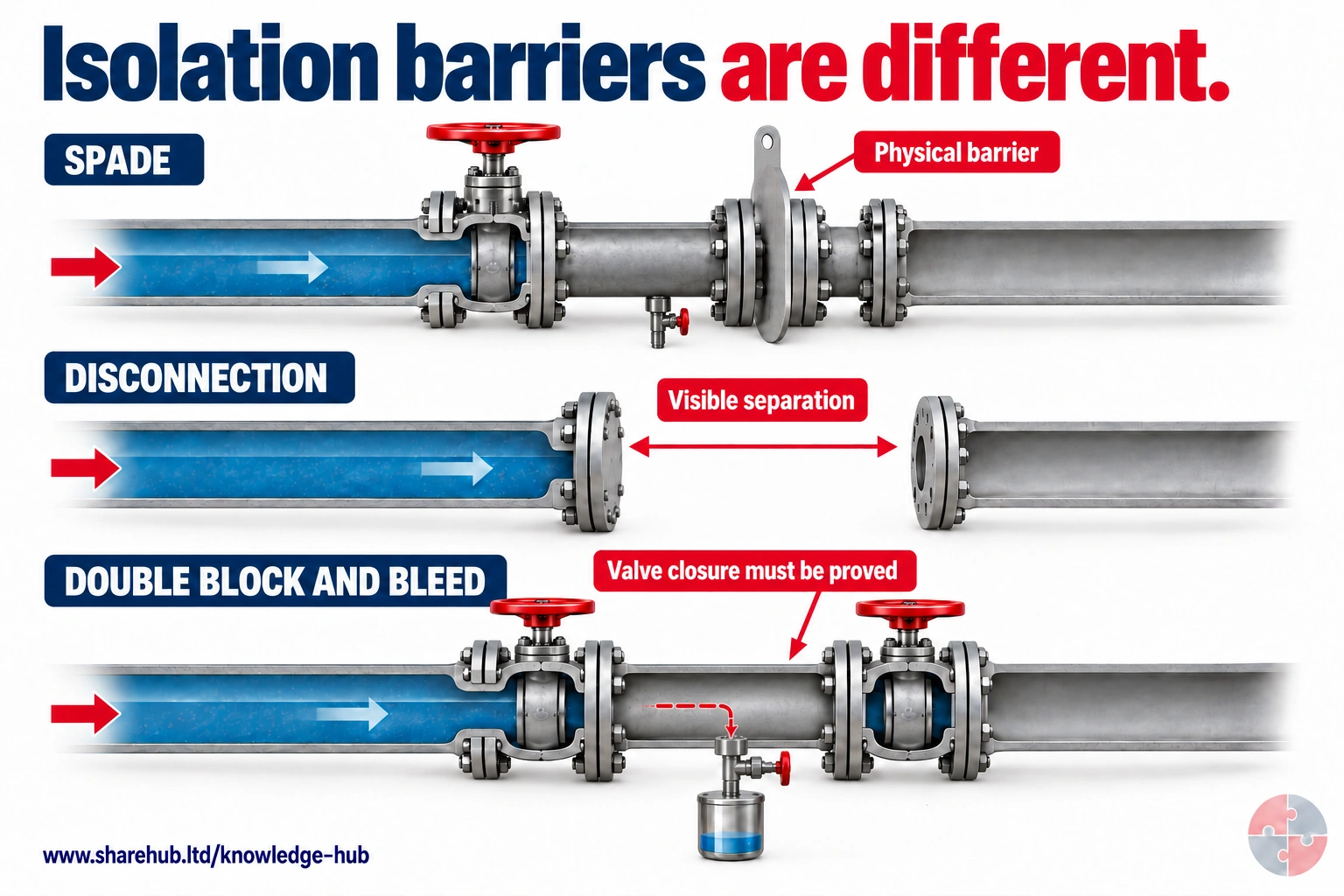
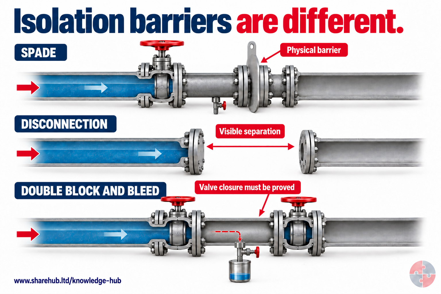
The DBB example keeps the same main-pipe bore through both block valves and the cavity between them. A smaller, separately valved bleed branches from that cavity for controlled draining, depressurisation and proving. A spade or visible disconnection provides a different barrier from closed valves; valve position alone does not prove isolation.
How does the small bleed connect to the main line?
It branches from the cavity between the two block valves. The main pipe stays full size; the branch provides a controlled route for draining or depressurising that space and supporting proving. Its sizing, routing, operation and monitoring must be specified for the actual isolation.
Conceptual comparison only. Isolation selection, installation, bleed position and proving require a task-specific competent scheme under HSG253.
Source guidance: HSE HSG253
A lock may prevent operation, while a valve may still pass and a drain may leave trapped pockets. Match each energy source to a physical isolation, an independent proof method and a record at the point of work. HSG253 - The safe isolation of plant and equipment.
For a hydrocarbon line, identify every connected feed, pressure source and trapped pocket on the plant, then agree an isolation boundary that can be proved at the work point. A competent isolator applies the devices, drains and tests the section; an independent checker challenges line identity and test results before a controlled first break. If a valve passes or pressure returns, the team stops and re-establishes containment. HSE HSG253 treats isolation selection and proof as connected decisions, not separate paperwork.
| Isolation type | Typical method | Verification |
|---|---|---|
| Electrical isolation | Open isolator, remove fuse, lock off and tag. | Prove dead with approved tester and prove tester before/after. |
| Mechanical isolation | Block, chock, pin, disengage or restrain moving parts. | Physical check that movement cannot occur. |
| Valve isolation | Close and lock valves. | Bleed/drain test and check valve passing risk. |
| Positive isolation | Insert blind/spade, remove spool or physically disconnect. | Visual confirmation and blind register. |
| Double block and bleed | Two isolation valves with bleed between. | Use the competent approved proving scheme to prove each part of the arrangement separately, including both DBB valves/barriers, against its acceptance criteria and safe bleed/vent destination. See verification; do not assume one bleed observation proves both barriers or that a bleed must always remain open. |
| Supplementary control inhibition | Inhibit control signals or automation only after hazardous energy has been physically isolated, locked off and proved safe. | Verify the physical isolation first; check and control any bypass or override. Control-circuit switching alone is not electrical isolation. |
| Process cleaning/purging | Remove hazardous contents before opening. | Gas test, sample, pH or cleanliness confirmation. |
How does HSG253-style isolation thinking help?
HSG253 encourages a structured, risk-based approach to selecting and verifying isolation standards.
HSG253 is especially important for process industries because it treats isolation as a barrier system. The isolation standard should match the consequence of failure, the substance, pressure, temperature, inventory, line size, valve reliability, duration of work and whether people will break containment or enter equipment. See HSG253 - The safe isolation of plant and equipment.
A low-risk water line may not need the same isolation standard as a toxic, flammable, high-pressure or hot process line. But the decision must be deliberate, documented and competent, not based on convenience.
- What is the substance? — Toxic, flammable, corrosive or asphyxiant materials need stronger controls. Positive isolation for toxic gas line.
- What is pressure and temperature? — Stored energy changes consequence. Cool/depressurise steam before breaking flange.
- How reliable are valves? — Passing valves can defeat isolation. Use double block and bleed or spade.
- How intrusive is work? — Line breaking and vessel entry need higher assurance. Blind register and permit hold point.
- How long will isolation remain? — Long duration increases change and handover risk. Shift handover and isolation audit.
- What if isolation fails? — Consequence drives baseline standard. Escalate to engineering authority.
How should isolation work be planned?
Planning should start before the permit is issued and should involve operations, maintenance and competent technical input.
A strong plan identifies the work scope, isolation boundary, energy sources, drain/vent points, line contents, drawings, lock points, verification method, PPE, access, SIMOPS, emergency arrangements and handback requirements. It also defines who applies, verifies, accepts and removes isolations. See HSG253 - The safe isolation of plant and equipment; HSG250 - Guidance on permit-to-work systems.
A weak plan relies on memory or inherited labels. Older plant, temporary hoses, bypasses, cross-connections, dead legs and undocumented changes make physical verification essential.
- Scope definition — Prevents isolating the wrong plant or too little plant. Permit scope and marked-up drawing.
- Energy inventory — Identifies all supplied and stored energy. Isolation plan and walkdown notes.
- Isolation method — Sets valve, blind, electrical and mechanical controls. Isolation certificate.
- Verification method — Defines how zero energy will be proved. Test/bleed/gas-test record.
- Roles — Clarifies authoriser, isolator, accepter and verifier. Permit role signatures.
- Emergency plan — Sets response if release or exposure occurs. Rescue/spill/fire arrangements.
How should isolation be verified?
Verification proves the isolation is effective at the point of work, not just applied somewhere upstream.
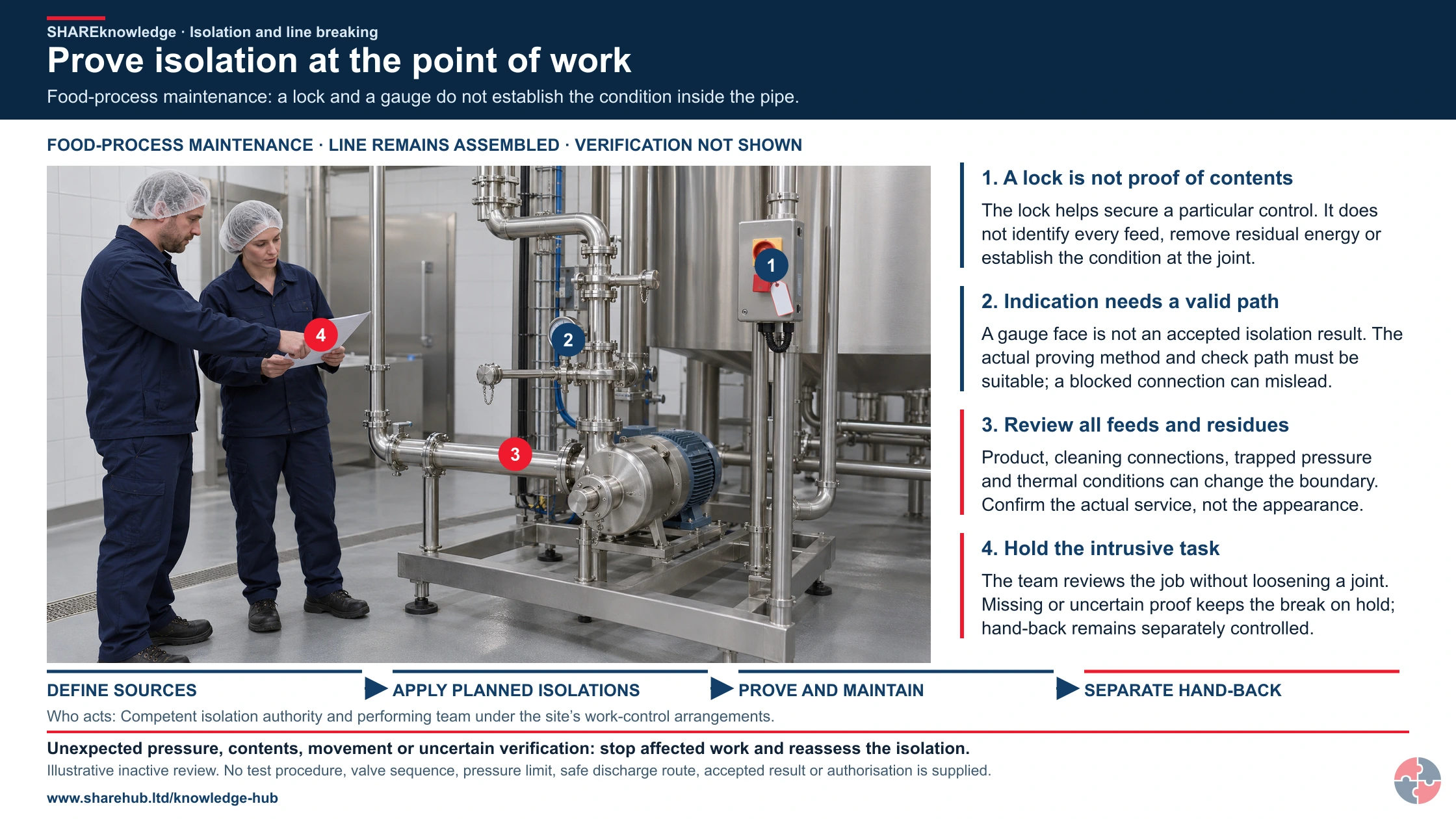
Prove isolation at the point of work
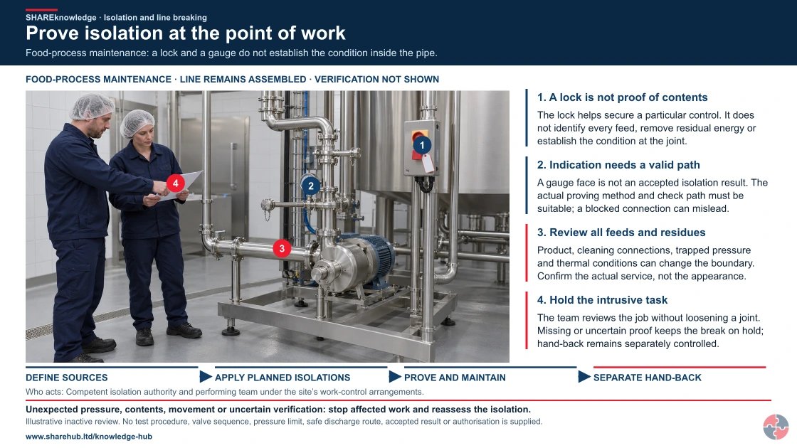
Full written explanation
A new realistic food-process maintenance review scene shows two colleagues discussing a job sheet beside intact stainless pipework and an inactive pump skid. A local switch carries a lock and blank tag, while a gauge, upper pipe connection and assembled joints remain visible. Native numbered labels distinguish securing a control from knowing contents, question the validity of the proving path, include other product/cleaning and thermal sources, and keep the intrusive break on hold while proof is unresolved. No person operates, opens, tests or loosens the equipment. The four original source checks—define every source, apply suitable planned isolations, prove effectiveness, and control work and return—remain in the full written route. The scene demonstrates neither a readable accepted result nor effective isolation, safe depressurisation/drainage, a valve sequence, a safe disposal destination, work permission or completed hand-back.
Food-process maintenance: a lock and a gauge do not establish the condition inside the pipe.
- Define every source. Identify the exact work point, connected supplies, stored energy and possible backfeed.
- Apply suitable isolations. Competent people use the planned boundary, secure it and control associated contents.
- Prove effectiveness. Use a suitable workface verification method; a lock, closed valve or zero gauge alone is insufficient.
- Control the work and return. Maintain the boundary, manage any first break and use separate hand-back/restoration authority.
When the evidence does not fit: Unexpected pressure, contents, movement or uncertain verification: stop affected work and reassess the isolation.
Who acts: Competent isolation authority and performing team under the site’s work-control arrangements.
Changed workplace
Chemical plant: Connected sources, passing valves and hazardous contents need a defined verification route.
Food-process maintenance: Cleaning, thermal energy, pressure and product connections may create different isolation needs.
Evidence check: The proving path must itself be suitable and effective; an unreadable or blocked check is not proof.
Use the complete isolation, verification and physical-method explanations
Primary references: HSE HSG253: safe isolation guidance · HSE HSG253: process isolation, proving and monitoring · HSE: competent maintenance and stored energy
Open the complete HD image (new tab)Download image
Use the complete isolation, verification and physical-method explanations
Primary references: HSE HSG253: safe isolation guidance · HSE HSG253: process isolation, proving and monitoring · HSE: competent maintenance and stored energy
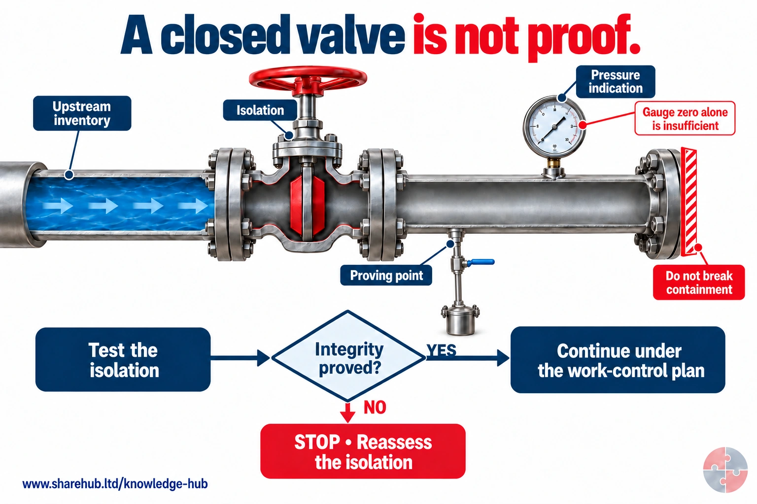
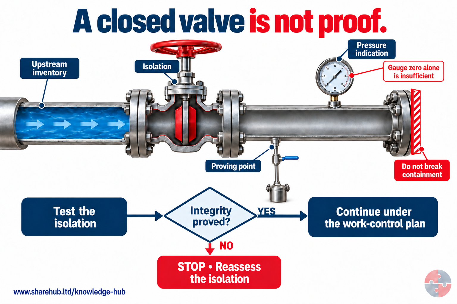
The cutaway separates valve closure, pressure indication and a controlled proving connection. A zero gauge reading alone cannot establish complete depressurisation or prove that the small-bore test path is clear. The NO branch stops intrusive work; a successful test leads only to the remaining authorised work controls.
What should happen when isolation cannot be proved?
Stop intrusive work and reassess the isolation and test arrangement rather than breaking containment to find out.
Conceptual hold point, not a test procedure or a sufficient isolation scheme. Define the test method, acceptance criteria, safe discharge route and monitoring in the competent work plan; check for leakage or pressure build-up immediately before breaking containment and as required during the work.
Source guidance: HSE HSG253
See the isolation boundary in physical form
Compare eight arrangements from HSG253 Figure 4. These original equipment illustrations explain the geometry and evidence; they do not select or authorise a scheme for your plant. Choose an arrangement, then open its proof and failure explanations.
8 isolation arrangements
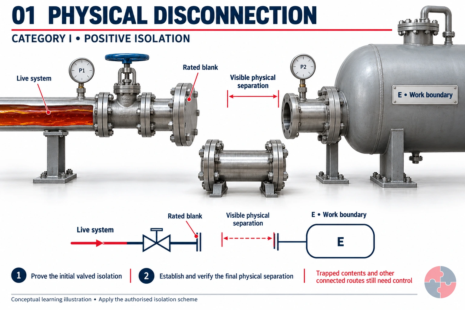
A removed spool leaves a visible gap. A suitable blank closes the live end; the separated equipment still has to be checked for other feeds, pressure and retained contents.
How this barrier is verified
Confirm the correct break location, a genuinely complete disconnection, the specified blank and its installed condition. Prove the temporary valved scheme used for installation, then the final positive isolation using the authorised method.
What can invalidate the conclusion?
Visible separation is strong evidence of that particular route being broken. It does not identify every other route into the equipment or remove trapped inventory.
Read the physical layout
Positive isolation creates a physical separation. Installing or removing the blank is itself intrusive work and requires an appropriate proved initial isolation.
Why is the air gap not the whole isolation plan?
The equipment can have other connections and retained energy. The identified work boundary and every relevant feed still require verification.
Conceptual comparison of isolation methods, not a valve-operating or line-breaking procedure. The competent isolation plan must define the pressure differential, test duration, acceptance limits, safe discharge destination, bleed positions, monitoring and authorisation for the actual service. Do not open a flange to discover whether an isolation holds.
Source guidance: HSE HSG253
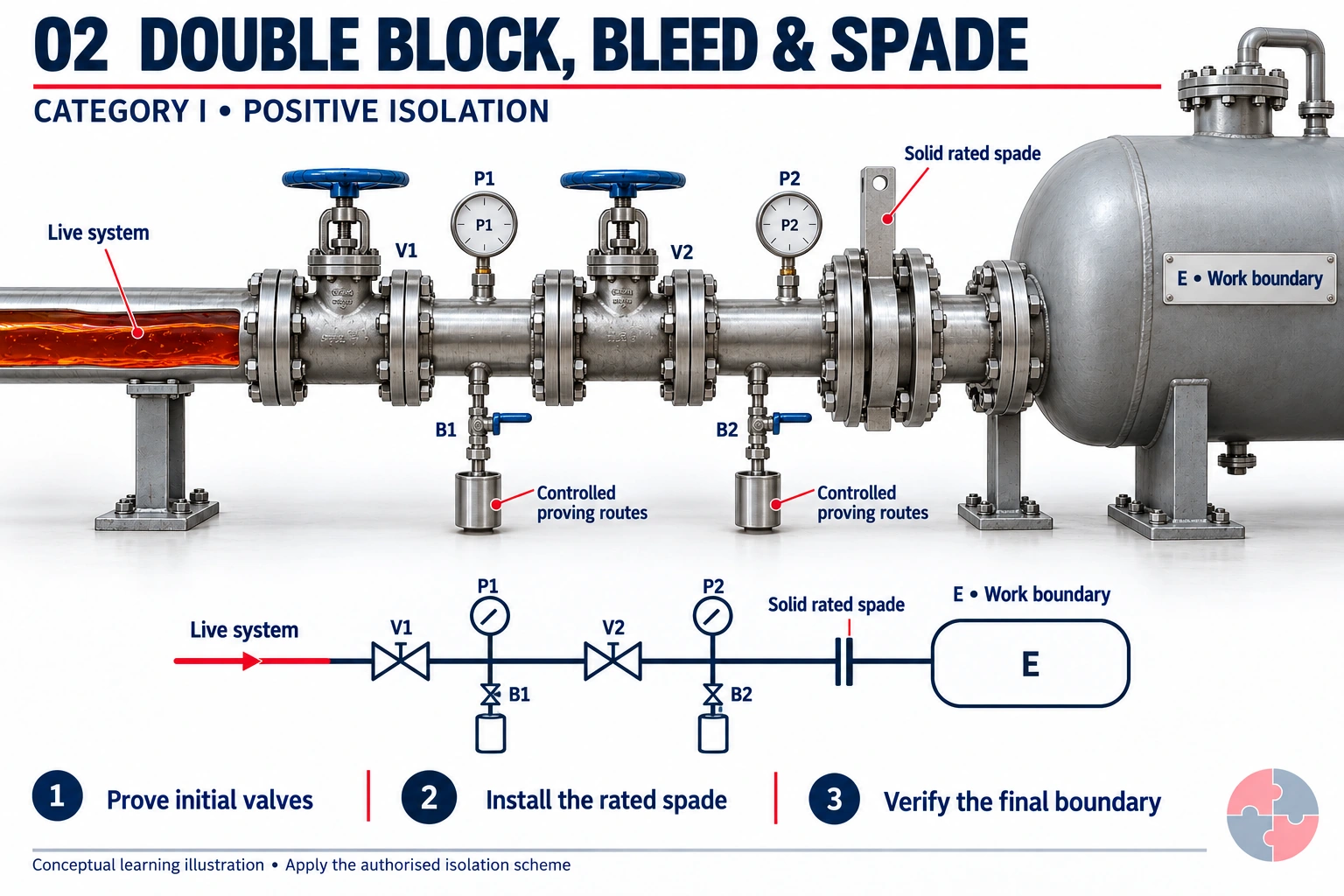
Two block valves and controlled test connections support the initial isolation. The installed solid spade provides the final physical barrier to the equipment.
How this barrier is verified
Establish the valve identities and prove each specified valve barrier separately. Control the intervening and downstream cavities. Verify the spade's identity, suitability, position and installed joint, then prove the final boundary as specified.
What can invalidate the conclusion?
A tab is an identification aid, not proof that a correctly rated solid plate is installed and the joint is sound. Pressure can remain or return in the cavities.
Read the physical layout
The diagram's P1/B1 cavity is between V1 and V2. P2/B2 is downstream of V2 and upstream of the spade. Collection fittings represent a controlled proving destination, not a universal drain arrangement.
What distinguishes this from double block and bleed alone?
The solid inserted spade provides a positive physical barrier. The initial valve scheme and final positive isolation both require their own verification.
Conceptual comparison of isolation methods, not a valve-operating or line-breaking procedure. The competent isolation plan must define the pressure differential, test duration, acceptance limits, safe discharge destination, bleed positions, monitoring and authorisation for the actual service. Do not open a flange to discover whether an isolation holds.
Source guidance: HSE HSG253
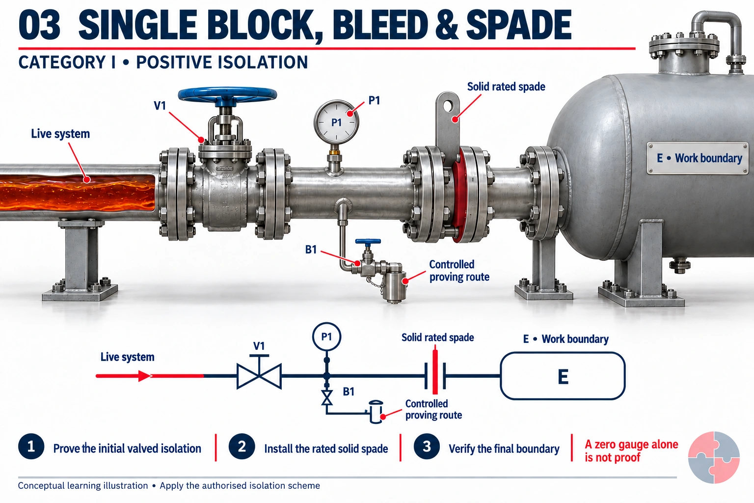
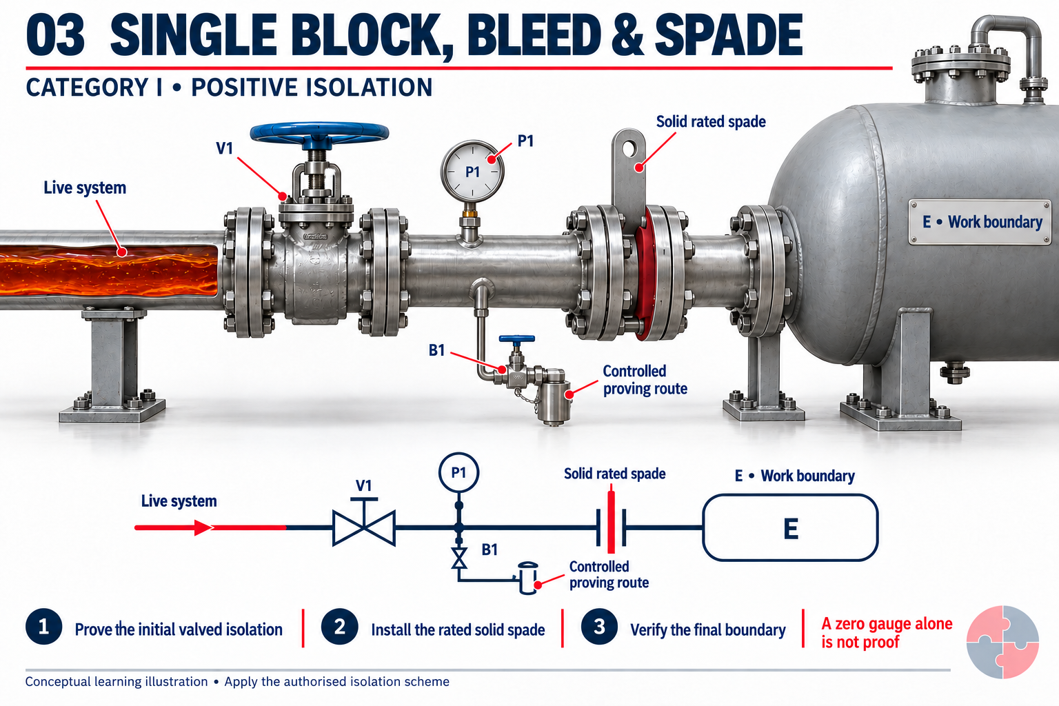
The final barrier is a solid spade. One valve and a controlled bleed support its installation; that initial valved arrangement needs a separate risk assessment.
How this barrier is verified
Prove the initial valved isolation with the planned test facilities and acceptance criteria. Confirm the rated solid spade is correctly installed, then verify the final isolation boundary and retained contents.
What can invalidate the conclusion?
The final spade does not make its installation risk-free. A passing valve or blocked bleed can compromise the initial work stage.
Read the physical layout
A zero pressure indication alone is insufficient. Do not treat this illustration as approval to install a spade behind one valve in a hazardous service.
Why must the initial isolation be assessed separately?
Inserting the spade requires breaking containment before the final solid barrier exists. A suitable initial scheme must protect that work.
Conceptual comparison of isolation methods, not a valve-operating or line-breaking procedure. The competent isolation plan must define the pressure differential, test duration, acceptance limits, safe discharge destination, bleed positions, monitoring and authorisation for the actual service. Do not open a flange to discover whether an isolation holds.
Source guidance: HSE HSG253
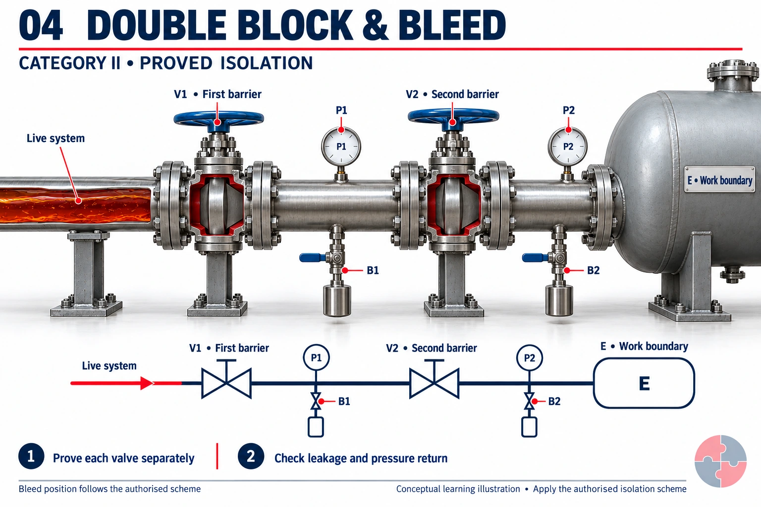
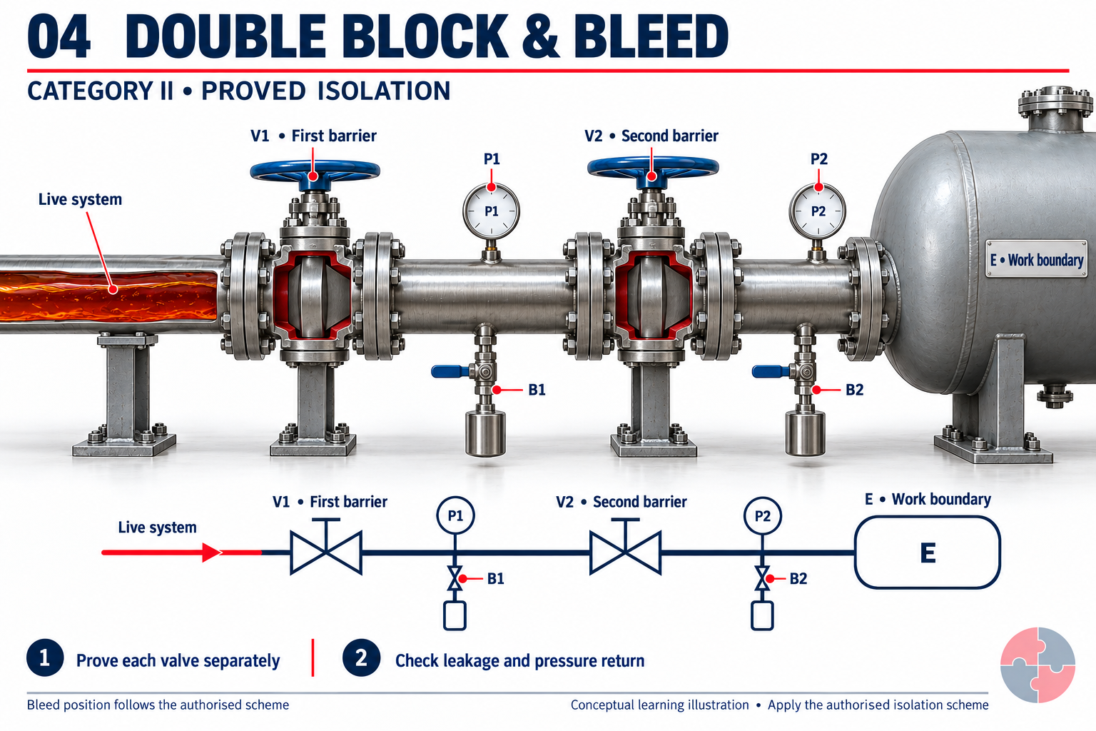
V1 and V2 are two separate valve barriers. The middle cavity and work-side test facilities allow their sealing functions to be examined under the planned scheme.
How this barrier is verified
Prove each valve separately against the relevant expected pressure and direction, using the specified test arrangement. Confirm the test paths work; observe leakage or pressure return against defined limits and record the result.
What can invalidate the conclusion?
Two closed handwheels are not two proved barriers. Debris, seat damage, reverse pressure or a blocked small-bore connection can defeat the assumption.
Read the physical layout
The illustration shows test facilities, not a universal valve sequence. Final bleed positions depend on the risk assessment and whether a connected disposal system can back-pressurise the cavity.
Does a quiet middle bleed prove both valves automatically?
No. Each specified barrier needs a suitable individual test. The pressure differential, test path and work-side condition matter.
Conceptual comparison of isolation methods, not a valve-operating or line-breaking procedure. The competent isolation plan must define the pressure differential, test duration, acceptance limits, safe discharge destination, bleed positions, monitoring and authorisation for the actual service. Do not open a flange to discover whether an isolation holds.
Source guidance: HSE HSG253
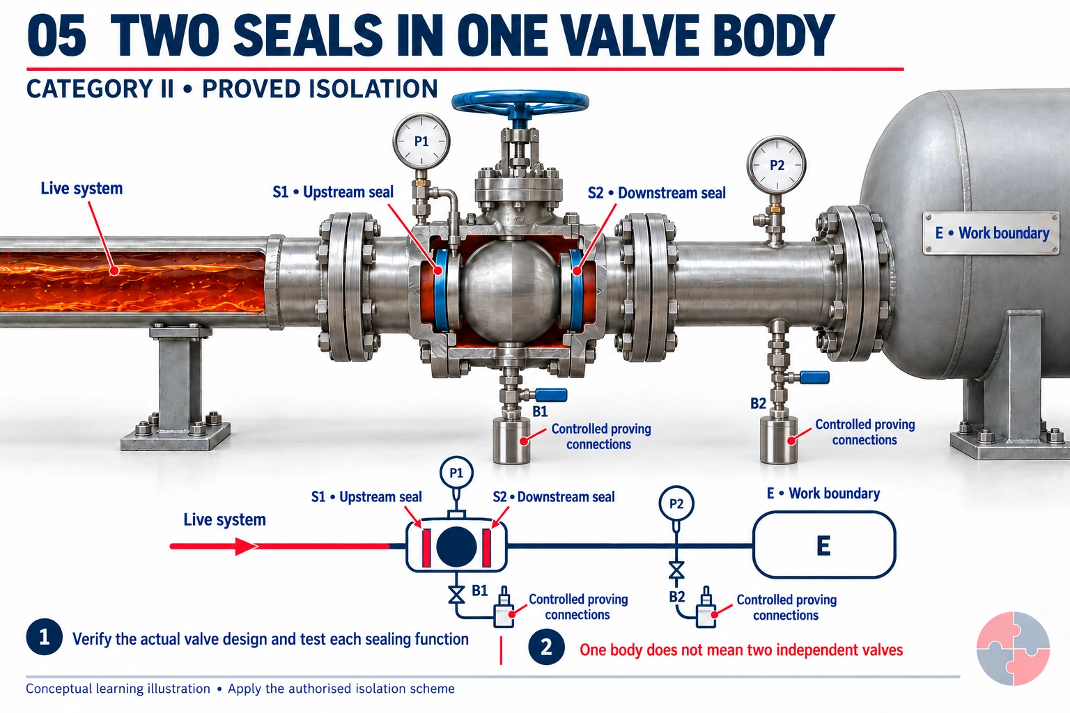
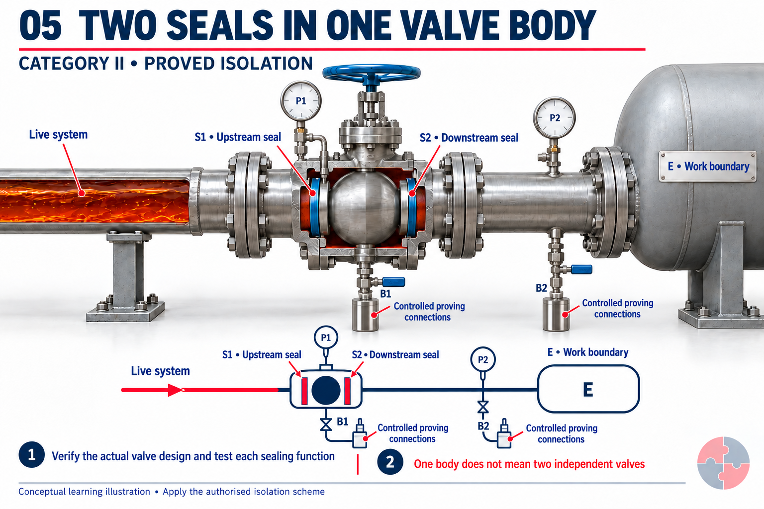
Two seat sealing functions share one valve body. A cavity bleed connects between them. This differs from two separate valve bodies.
How this barrier is verified
Check the actual valve design, service suitability, seating behaviour and cavity connections. The authorised arrangement must allow the specified sealing functions to be tested separately and any leakage or pressure return to be detected.
What can invalidate the conclusion?
Seat design, pressure direction and a common body can affect the protection provided. A manufacturer's DBB label alone does not establish the required independence or testability.
Read the physical layout
The cutaway is illustrative, not a valve design specification. Verify the manufacturer's actual sectional drawing and testing limitations before selecting the valve for an isolation scheme.
Are two seats automatically equivalent to two separate valves?
No. Identify what each seat does, which pressure directions it seals and how its effectiveness can actually be proved.
Conceptual comparison of isolation methods, not a valve-operating or line-breaking procedure. The competent isolation plan must define the pressure differential, test duration, acceptance limits, safe discharge destination, bleed positions, monitoring and authorisation for the actual service. Do not open a flange to discover whether an isolation holds.
Source guidance: HSE HSG253
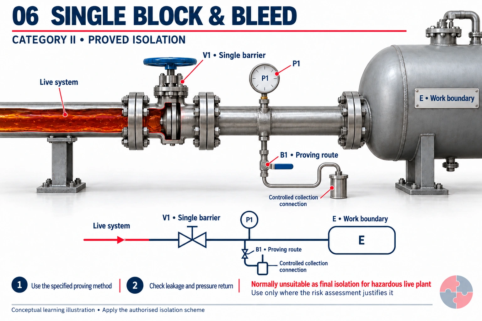
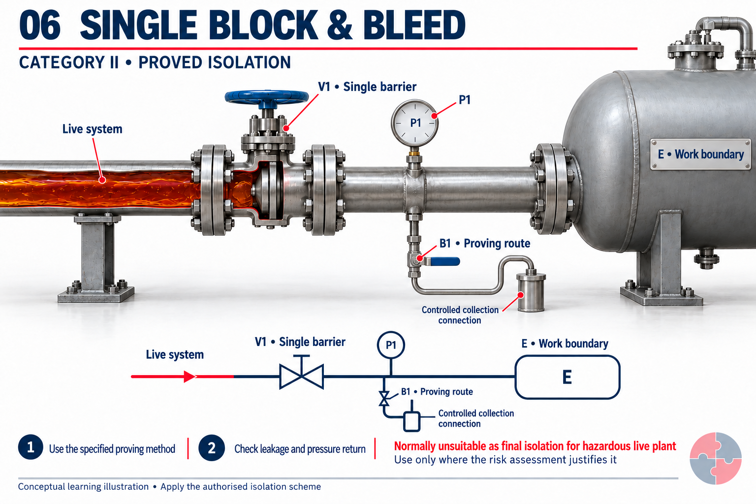
One closed valve is the sole valved barrier. A downstream controlled bleed and pressure facility provide a means of checking that barrier.
How this barrier is verified
Confirm the test path is clear and appropriate, then prove the valve under the planned pressure conditions and acceptance criteria. Verify the work-side inventory and continue the specified monitoring.
What can invalidate the conclusion?
There is no second valve barrier if the seat passes. HSG253 generally discourages SBB as final isolation for intrusive work on live plant with hazardous substances; any use needs a justified risk assessment.
Read the physical layout
This is a comparison of method and limitation. The illustration does not recommend SBB for a particular substance, pressure or job.
What is the principal limitation of SBB?
A single valve provides the only valved barrier. Having a bleed does not create a second independent block.
Conceptual comparison of isolation methods, not a valve-operating or line-breaking procedure. The competent isolation plan must define the pressure differential, test duration, acceptance limits, safe discharge destination, bleed positions, monitoring and authorisation for the actual service. Do not open a flange to discover whether an isolation holds.
Source guidance: HSE HSG253
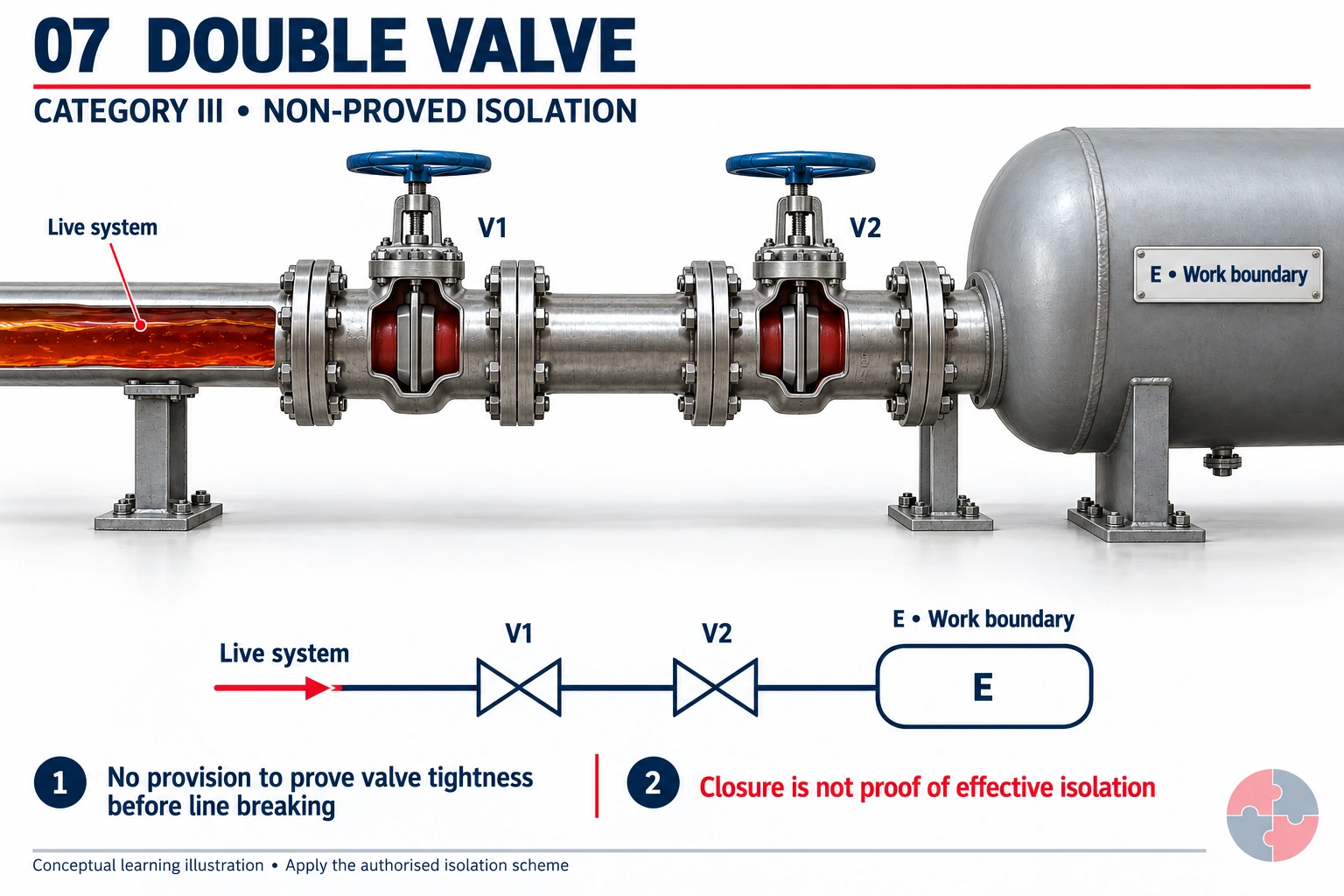
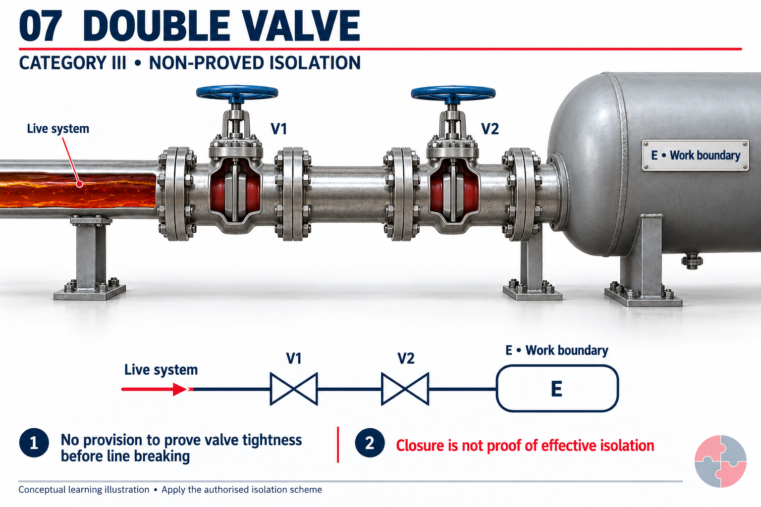
Two valves are closed, but the depicted arrangement has no facilities to establish their tightness before breaking into the system.
How this barrier is verified
The shown arrangement cannot provide the same pre-break proof as a suitably testable scheme. If proof is required, improve or extend the isolation arrangement or replan the work, including shutdown where appropriate.
What can invalidate the conclusion?
Locks, position indicators and an absence of visible flow do not demonstrate leak-tight seats. Do not crack a flange as a test.
Read the physical layout
Category III is explicitly non-proved. Its acceptability must come from the task-specific risk assessment and authorised scheme, not the number of valves in the image.
What is missing despite the two closed valves?
A suitable way to prove the effectiveness of the valve closures before breaking containment.
Conceptual comparison of isolation methods, not a valve-operating or line-breaking procedure. The competent isolation plan must define the pressure differential, test duration, acceptance limits, safe discharge destination, bleed positions, monitoring and authorisation for the actual service. Do not open a flange to discover whether an isolation holds.
Source guidance: HSE HSG253
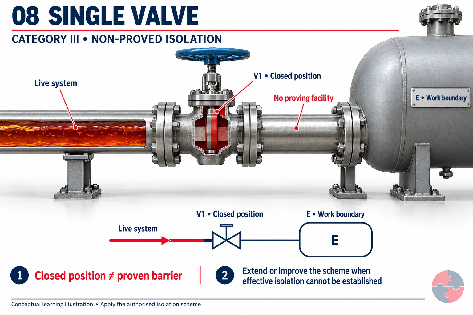
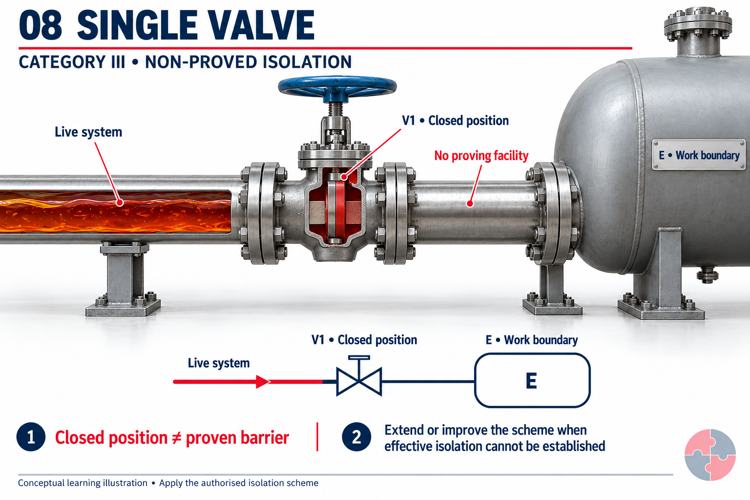
One valve is shown in the closed position with no bleed or monitoring facility. The picture demonstrates position, not verified isolation.
How this barrier is verified
Identify the missing proof and the required work boundary. Do not infer tight shut-off from a closed handle; use the competent planning route to improve the arrangement, extend the boundary or defer the work as necessary.
What can invalidate the conclusion?
A locked valve can still pass or be the wrong valve. No depicted instrument or test route establishes its effectiveness.
Read the physical layout
A non-proved arrangement is not transformed into a proved barrier by a permit, lock, tick-box or illustrative diagram.
Can a closed handle and lock prove the barrier is holding?
No. They help control position and unauthorised operation; they do not establish the valve's sealing effectiveness.
Conceptual comparison of isolation methods, not a valve-operating or line-breaking procedure. The competent isolation plan must define the pressure differential, test duration, acceptance limits, safe discharge destination, bleed positions, monitoring and authorisation for the actual service. Do not open a flange to discover whether an isolation holds.
Source guidance: HSE HSG253
Read the labels: E is the equipment/work boundary. P identifies a pressure-monitoring facility; B identifies a controlled bleed/test route. Test-path design, destination and bleed position must follow the authorised scheme. A gauge reading or a closed valve alone is not proof. Collection symbols mark the need for a specified controlled route; they do not prescribe a vessel, capacity or bleed-valve position.
Verification is the difference between a hopeful isolation and a controlled job. Electrical work needs proving dead; process work may need depressurisation, drain/vent checks, gas testing, sampling, pressure indication, bleed verification, flushing, purging or visual confirmation of blinds. See HSG253 - The safe isolation of plant and equipment.
Verification should be independent enough for the risk. A person should not simply trust the same label or drawing that could be wrong. Where consequences are high, independent verification and authoriser challenge are essential.
| Hazard | Verification method | Common failure |
|---|---|---|
| Electrical energy | Test for dead with approved voltage indicator. | Tester not proved before/after or wrong circuit tested. |
| Pressure | Check gauges, vents, drains and bleed points. | Blocked gauge line gives false reading. |
| Flammable atmosphere | Gas test after purge and before line break. | Single test misses later vapour return. |
| Toxic/corrosive contents | Sample, drain, flush, isolate and PPE. | Dead leg or trapped pocket remains. |
| Mechanical movement | Try-start where safe, block and physical check. | Stored gravity/hydraulic energy not controlled. |
| Blind/spade | Visual check and blind list verification. | Wrong size/rating or wrong location. |
Learning check: two apparent protections
A locked but wrongly identified isolator does not protect the work point. A correctly identified boundary still requires proof of every relevant energy/feed and each specified DBB barrier, with accepted evidence and a safe discharge destination. If identity or proof is missing, hold the intrusive work and use the roles/competence route. Do not turn this check into a generic valve-operating sequence or invent acceptance pressures.
What makes line breaking especially hazardous?
Line breaking is the point where containment is opened and hidden assumptions are tested.
The first crack of a flange can release pressure, vapour, liquid, sludge, solids, steam, corrosive material, toxic gas or flammable atmosphere. Even a small residual quantity can injure a worker if it is hot, under pressure, toxic or reactive. See HSG253 - The safe isolation of plant and equipment.
Line breaking should therefore use a deliberate break plan: verify isolation, control drainage, position workers out of the line of fire, loosen bolts cautiously, use drip trays or containment, wear task-specific PPE, control ignition sources and stop if unexpected pressure or material appears.
| Control point | Why it matters | Good evidence |
|---|---|---|
| Line contents known | Controls depend on substance. | SDS/process data and sampling where needed. |
| Pressure removed | Prevents violent release. | Vent/drain verification. |
| Worker position | Avoids line of fire. | Pre-job briefing and observation. |
| Containment | Controls spills and exposure. | Drip tray, bunding or drain isolation. |
| PPE/RPE | Protects against residual risk. | Task-specific PPE assessment. |
| Stop criteria | Controls unexpected release. | Briefed hold points. |
How should lockout and tags be managed?
Locks and tags communicate and enforce the isolation status, but they only work inside a disciplined system.
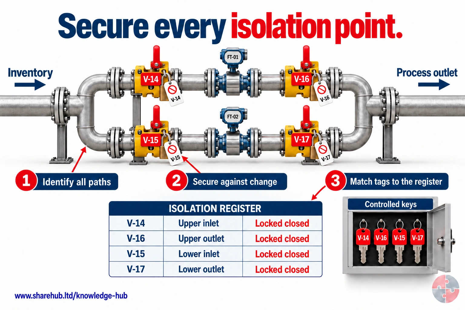
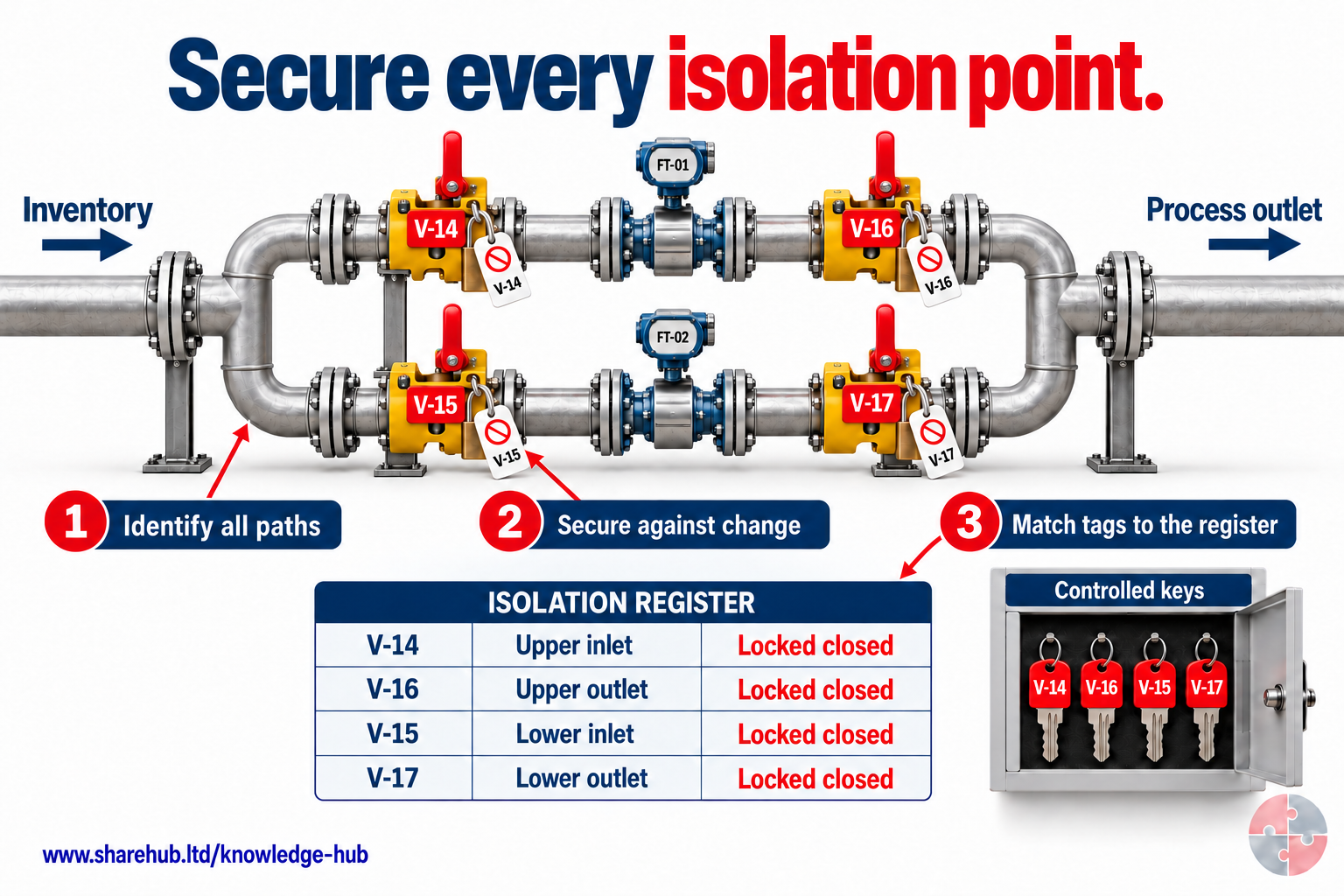
FT-01 sits between V-14 and V-16; FT-02 sits between V-15 and V-17. Each instrument has an inlet and an outlet isolation valve, shown locked closed. All four tags match the register and controlled keys. Check both sides and every connected route; locking does not prove that an instrument is depressurised.
Why check the outlet valve as well as the inlet?
A common outlet or another connected branch may expose the instrument to pressure or backflow. Identify every relevant route, secure the specified isolation points, prove the isolation and safely deal with trapped contents and other energy before intrusive work.
Conceptual instrument-isolation example. Locks and a matching register do not prove zero pressure. Trapped contents, instrument power, safe draining, proving and restoration of control functions require a competent task-specific scheme.
Source guidance: HSE HSG253
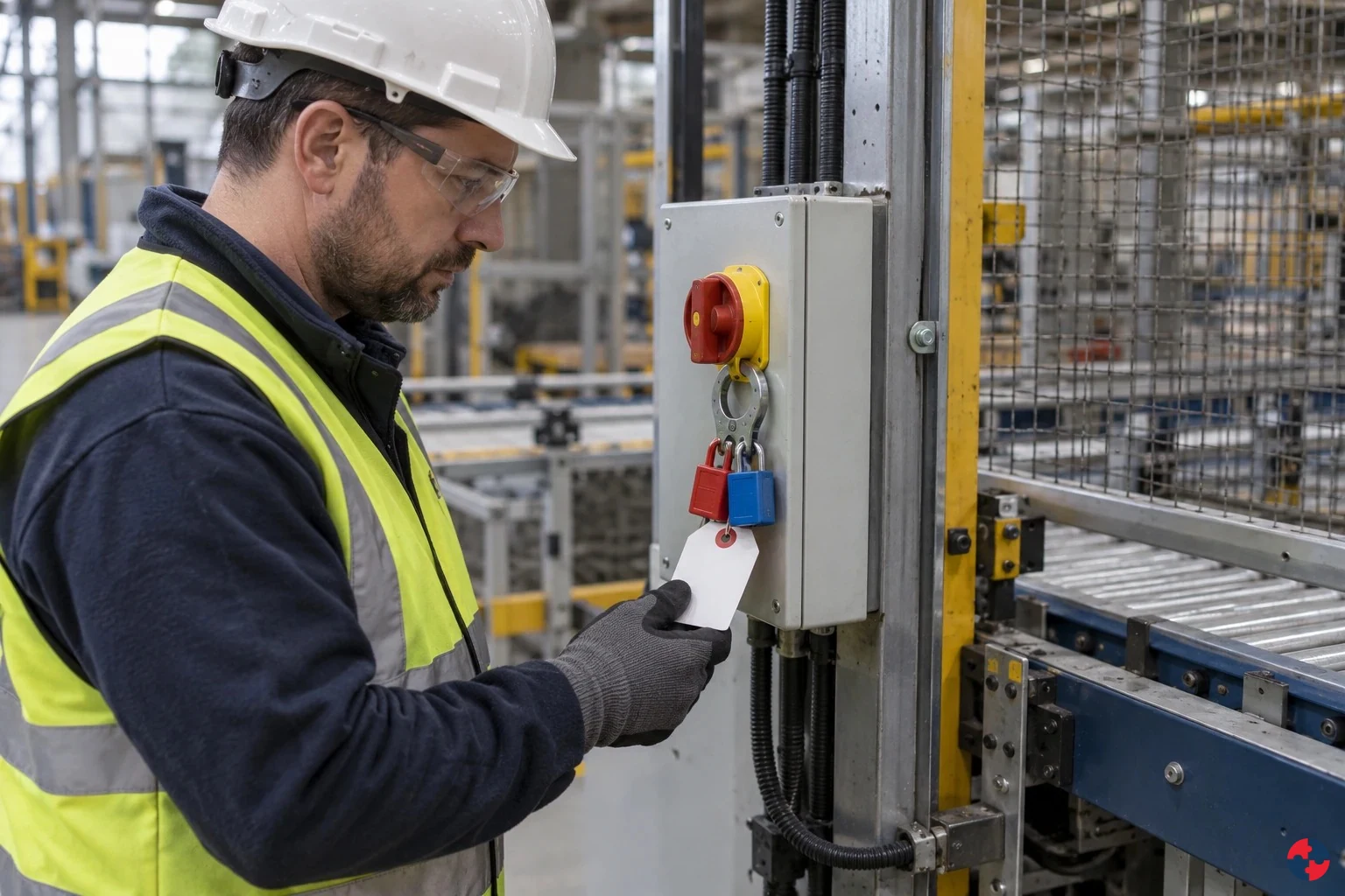
Lockout should make unauthorised operation physically difficult or impossible. Tags explain who applied the isolation, why it is there, what work it supports and what must not be operated. Personal locks, group lock boxes, lock registers and key control prevent the dangerous ambiguity of shared informal locks. See HSG253 - The safe isolation of plant and equipment.
Tag-only systems are weak where re-energisation would cause serious harm. A tag is communication; a lock is physical control.
- Personal lock — Worker controls own protection where appropriate. One supervisor lock protects everyone without clear handover.
- Group lock box — Controls multiple isolation points for group work. Keys stored loosely in control room.
- Tag information — Identifies job, person, permit and date. Old tag left with no owner.
- Lock removal rule — Formal process for absent worker or emergency removal. Anyone cuts lock to restart plant.
- Audit — Field checks verify locks match certificate. Only permit desk checks paperwork.
How do permits and isolation certificates work together?
The permit controls the work; the isolation certificate records the specified isolation and verification evidence.
A permit to work should not be treated as proof that isolation is safe. It should reference an isolation certificate, marked-up drawing, blind list, gas-test record, lock register or other evidence. The authoriser must be satisfied that the isolation matches the job scope. See HSG250 - Guidance on permit-to-work systems.
If the job scope changes, the isolation may no longer be valid. A small change from inspection to flange removal, or from cold work to hot work, can change the isolation standard, gas testing and emergency requirements.
- Scope match — Permit task and isolation boundary describe same plant. Permit and isolation certificate cross-reference.
- Hold points — Line break, gas test, blind insertion and handback points controlled. Authoriser sign-off.
- SIMOPS — Other work cannot defeat isolation. SIMOPS review.
- Gas testing — Atmosphere safe for task and remains controlled. Initial and repeat gas test record.
- Reinstatement — Locks, blinds, drains, vents and valves restored deliberately. Handback checklist.
How should handover and handback be controlled?
Isolation risk increases during shift change, job pause, recommissioning and return to service.
Handover must explain what is isolated, what is open, what is drained, what is blinded, which locks are applied, what work is incomplete and what must not be operated. Incoming teams should not inherit assumptions without walking down critical isolations where risk justifies it. See HSG253 - The safe isolation of plant and equipment.
Handback is not just removing locks. It includes checking tools and people are clear, blinds and spades are removed or correctly positioned, drains and vents are closed, guards are replaced, leak testing is complete, alarms/interlocks are restored, overrides are removed and the system is safe for restart.
- Shift handover — Status misunderstood. Written and verbal isolation handover.
- Job suspended — Plant condition changes while work paused. Suspend permit and secure open systems.
- Reinstatement — Blind, lock or drain left in wrong state. Reinstatement checklist and second check.
- Leak test — Containment not proven. Controlled pressurisation and inspection.
- Restart — People or tools remain in danger zone. Final sweep and authorisation.
How do simultaneous operations affect isolation?
SIMOPS can defeat isolation if teams work on connected systems without shared understanding.
When another team changes a connected line or control system, the original isolation assumptions may cease to hold. The area authority must coordinate the tasks, reassess the boundary and reverify before either team continues. HSG250 - Guidance on permit-to-work systems.
- Second team opens drain — Isolation boundary changes. SIMOPS board and permit coordination.
- Control room starts equipment — Remote operation defeats local assumptions. Verified physical energy isolation/lockout remains primary. Control inhibition, control-room handover and authorisation are supplementary and cannot alone isolate hazardous energy.
- Hot work nearby — Released vapour finds ignition source. Area coordination and gas testing.
- Contractor modifies pipework — Drawing no longer reflects reality. Management of change and redline update.
- Cleaning and maintenance overlap — Chemical or pressure introduced unexpectedly. Shared isolation plan and supervisor coordination.
Where do isolation and line-breaking systems commonly fail?
Common failures are usually predictable and should be designed out or caught by assurance.
Wrong line identity, passing valves, back-feed, blocked drains and incomplete handback can each defeat a signed plan. Treat these as testable failure modes with named checks, not as reminders to be careful.
- Wrong plant isolated — Labels, drawings or verbal instructions are wrong. Walkdown, prove at point of work and independent check.
- Valve passing — Isolation valve leaks internally. Bleed test, DBB or positive isolation.
- Stored energy remains — Accumulator, capacitor, spring, gravity or pressure not released. Energy inventory and verification.
- Back-feed — Secondary supply or process connection re-energises system. Identify all sources and lock them.
- Lock removed early — Poor key control or handover. LOTO procedure and lock removal rule.
- Scope creep — Task becomes more intrusive than authorised. Stop and reauthorise permit/isolation.
What evidence shows isolation is managed?
Evidence should prove the isolation was planned, applied, verified, maintained and removed safely.
Evidence should be read as a chain rather than a filing exercise. A single record rarely proves good management on its own; stronger assurance comes from matching records, observations, interviews, trends and verified action closure.
- Isolation certificate — Documents isolation points, locks and verification. Does it match the job scope?
- Marked-up P&ID/drawing — Shows boundary and connected systems. Is it current and field checked?
- Blind/spade register — Controls positive isolation hardware. Are blinds rated, tagged and signed in/out?
- Gas test/pressure/drain record — Shows safe condition before line break. Are repeat tests defined?
- Lock register — Controls keys and personal/group locks. Can every lock be traced?
- Handover log — Maintains status across shifts. Does incoming team understand status?
- Audit sample — Checks field isolation matches paperwork. Are findings closed and trended?
How should a line-breaking job be controlled?
A worked example shows how theory becomes a safe job plan.
A maintenance team must replace a gasket on a flammable hydrocarbon pump discharge line. The weak approach is to shut the pump, close one valve, issue a permit and crack the flange. The strong approach identifies all feeds, reverse flow, trapped pressure, drain points, ignition sources, pump auto-start, control-room status, relief paths, SIMOPS and emergency arrangements. See HSG253 - The safe isolation of plant and equipment.
The job first establishes and proves suitable initial process and electrical isolation. The isolated section is then safely depressurised, drained and purged as the assessment requires. Only then is a blind, spade or physical disconnection installed under a separate controlled first-break method and proved as the specified positive isolation. The target gasket flange is opened only after the whole barrier set and atmosphere are verified.
For a learner or auditor, the important point is sequence. You do not start with a permit form; you start with the energy and loss-of-containment scenario. The permit then becomes the authorisation layer sitting on top of a verified physical barrier system.
- 1. Identify the job and equipment — Confirm the exact pump, line, flange, gasket and work scope using physical walkdown and drawings. Marked-up P&ID, equipment tag and job scope match.
- 2. Identify all energy and inventory — Review electrical supply, auto-start logic, upstream/downstream feeds, reverse flow, pressure, temperature, trapped liquid, vapour and relief paths. Energy inventory and isolation planning notes.
- 3. Select the isolation standard — Specify positive isolation, such as a correctly installed spade or blind, for this flammable hydrocarbon opening where the assessed standard requires it. A proved double-block-and-bleed arrangement is only an option if a competent HSG253 and site-standard assessment justifies it; a single closed valve is not the plan for this example. Record the authorised choice and its proof.
- 4. Isolate electrical and control energy — Stop the pump, open and lock the isolator, control auto-start and inhibit relevant control signals where needed. Lock register, control-room log and prove-dead record where applicable.
- 5. Establish and prove initial process isolation — Close and lock the selected initial process boundaries, identify all connections and independently prove the correct valves/line. Do not insert a spade or open a flange yet. Record valve IDs, checker and leak/pressure evidence.
- 6. Depressurise, drain and purge the isolated section — Vent and drain to the approved safe destination, purge when required and verify zero pressure and residual inventory at the intended installation point. Stop if pressure returns, a drain is blocked or the material identity is uncertain.
- 7. Install and prove specified positive isolation — Before this preparatory intrusive operation, obtain the appropriate authorised work control, including a separate or linked permit where the site system requires it, with a named responsible person and recorded prerequisites. Use its controlled first-break procedure, line-of-fire position, containment, atmosphere test and competent supervision to insert the assessed blind/spade or disconnect the section after depressurisation. Verify its identity and integrity before treating the target line as isolated.
- 8. Lock, tag and brief — Ensure locks and tags identify the isolation, permit, owner and date; brief workers on line of fire and stop criteria. Toolbox talk, lock box record and worker acknowledgement.
- 9. Authorise the target maintenance break after proved prerequisites — Authorise the target gasket line break only after initial isolation, depressurisation/purge and any positive isolation have been proved and recorded. Recheck the point of work, then open cautiously with workers out of the release path.
- 10. Reinstate and leak test — Replace gasket, remove temporary blanks only by procedure, close drains/vents, restore guards and test containment before returning to service. Reinstatement checklist, leak-test record and authoriser sign-off.
- 11. Hand back and learn — Remove locks/tags in sequence, update control room status, close permit and capture any passing valve, unexpected product or gas-test learning. Handback record, defect report and action tracker.
Opening a hydrocarbon pump discharge line
Task, material and setting: Maintenance must remove a pump spool in a fuel terminal. The line can hold hydrocarbon and pressure despite a stopped pump; another team is testing a connected system.
People and prerequisites: The area authority, operations isolator, maintainer and permit issuer verify line identity, process drawing, inventory, connected branches, drain destination and simultaneous operations.
Before: Establish and prove initial isolation; then safely depressurise, drain and purge the section. Insert and prove the specified blind/spade only through a separate controlled first break after zero-energy verification. Recheck the target line before maintenance.
During: Open the target gasket flange under controlled conditions with containment, ignition control, atmosphere test where needed and a defined escape route.
Hold or stop: Stop if pressure returns, the line identity is uncertain, isolation leaks, the drain path is blocked or the adjacent team changes the system.
Completion and hand back: After work, inspect the spool, remove blinds and locks only through authorised sequence, pressure-test where required, update the permit and hand back to operations before restart.
Evidence: Keep marked drawings, isolation certificate, independent check, locks, drain/test results, permit, SIMOPS coordination, first-break record and handback.
Which legal duties apply to isolation, lockout and line breaking?
Select the legal duties by location, equipment and material. In Great Britain, general risk duties sit alongside PUWER work-equipment duties and, where relevant, COSHH, DSEAR and electricity rules; Northern Ireland has separate counterparts. HSE HSG253 helps plan and verify process isolation, but it is guidance rather than a permit to break a line.
For a hydrocarbon flange, the responsible manager must decide who owns the plant, isolation boundary and restart, while the competent isolator proves the actual energy state. A signed permit or closed valve cannot establish zero pressure, chemical absence or protection against back-feed. Hold the first break if the line identity, draining, pressure test, atmosphere or independent check is uncertain; apply the matching GB or NI instruments in the table below.
| Jurisdiction | Duty route | Practical decision and evidence |
|---|---|---|
| Great Britain | Health and Safety at Work etc. Act 1974 and Management Regulations 1999 | Plan a safe system, assess hazardous energy and ensure competent supervision before intrusive work. Official text and guidance: Health and Safety at Work etc. Act 1974; Management of Health and Safety at Work Regulations 1999 |
| Northern Ireland | Health and Safety at Work (Northern Ireland) Order 1978 and Management Regulations (NI) 2000 | Apply the separate NI general duty and risk-management route to intrusive work and contractors. Official text and guidance: Health and Safety at Work (Northern Ireland) Order 1978; Management of Health and Safety at Work Regulations (NI) 2000 |
| Great Britain | Provision and Use of Work Equipment Regulations 1998 | Maintain suitable work equipment and isolation arrangements for maintenance and cleaning. Official text and guidance: Provision and Use of Work Equipment Regulations 1998; L22 - Safe use of work equipment |
| Northern Ireland | Provision and Use of Work Equipment Regulations (NI) 1999 | Apply NI equipment-use and maintenance duties; verify the isolation design against the actual plant. Official text and guidance: Provision and Use of Work Equipment Regulations (NI) 1999 |
| Great Britain | COSHH 2002 and DSEAR 2002, where hazardous substance or explosive atmosphere applies | Control residual chemicals, vapour, pressure and ignition during line-breaking; choose the isolation standard for the credible release. Official text and guidance: COSHH Regulations 2002; DSEAR Regulations 2002 |
| Northern Ireland | COSHH (NI) 2003 and DSEAR (NI) 2003, where applicable | Use the distinct NI hazardous-substances and explosive-atmosphere duties for process opening. Official text and guidance: COSHH Regulations (NI) 2003; DSEAR Regulations (NI) 2003 |
| Great Britain | Electricity at Work Regulations 1989 | Plan and verify electrical isolation, control back-feed and prove dead using a competent safe system. Official text: GB electricity regulations. |
| Northern Ireland | Electricity at Work Regulations (NI) 1991 | Apply the distinct NI electrical-duty route to lockout, back-feed and proving dead. Official text: NI electricity regulations. |
How could Crownway Fuels Ltd manage this in practice?

Crownway Fuels Ltd would plan intrusive maintenance around a verified isolation boundary and controlled work and reinstatement decisions, using competent people and the site's assessed standard.
Crownway Fuels Ltd · practical example
Define the process boundary before opening equipment
The key lesson An isolation boundary is an engineered and verified arrangement for the task, not simply a list of switches or valves.
The situation: A contractor is due to replace a component in a fuel-transfer line. The proposed work boundary crosses connected pipework and another maintenance job. A closed valve symbol on the drawing cannot establish the actual protected condition.
Why this matters: Residual pressure, hazardous contents or another connection can defeat assumptions made from a single device's position.
How Crownway Fuels Ltd would manage it
- Define the intrusive task — Maintenance Coordinator. Identify the exact equipment, connections and scope with operations and the contractor. Confirm the current plant information and identify related work that could affect the boundary.
- Specify the protection — Competent isolation authority. Determine the appropriate isolation standard, verification and handling of stored energy or contents under the approved system. Resolve technical uncertainty before approving the work package.
- Coordinate dependent work — Site Manager. Link the permit, isolation records and simultaneous activities. Make it clear who controls changes and ensure that another job cannot alter a protection on which this task relies.
- Confirm and maintain the boundary — Authorised permit issuer and acceptor. Use the site's required verification and briefing before releasing the defined task. Record status, restrictions and handover; do not extend the work beyond the assessed boundary.
- Control reinstatement separately — Authorised operating authority. Review completion, equipment condition and outstanding restrictions. Manage removal of protections and reinstatement through the approved sequence and communicate the accepted plant status to operations.
When the conditions change
- Recognise the trigger
- The work boundary, connected activity or verified isolation condition changes.
- Make the immediate decision
- Suspend the intrusive task when a connection, linked job or isolation condition differs from the accepted boundary.
- Verify the next step
- The competent isolation authority verifies the revised boundary and linked controls; the authorised permit issuer and acceptor confirm the specific work party and task before further intrusive work.
What good looks like
The protected boundary, actual equipment and work party's understanding agree. Linked jobs and stored-energy questions are resolved, and a completed repair does not silently release an isolation.
Evidence to look for: Current plant information, assessed isolation plan, verification records, linked permits, change history and accepted reinstatement.
Common mistake to avoid: Assuming a closed valve, lock or drawing symbol alone proves safe isolation.
Apply this to your work: Could another job change a protection your work party is relying on?
Guidance behind the management approach: HSE HSG253: safe isolation of plant and equipment. Use the topic's legal and technical guidance for the applicable work and location.
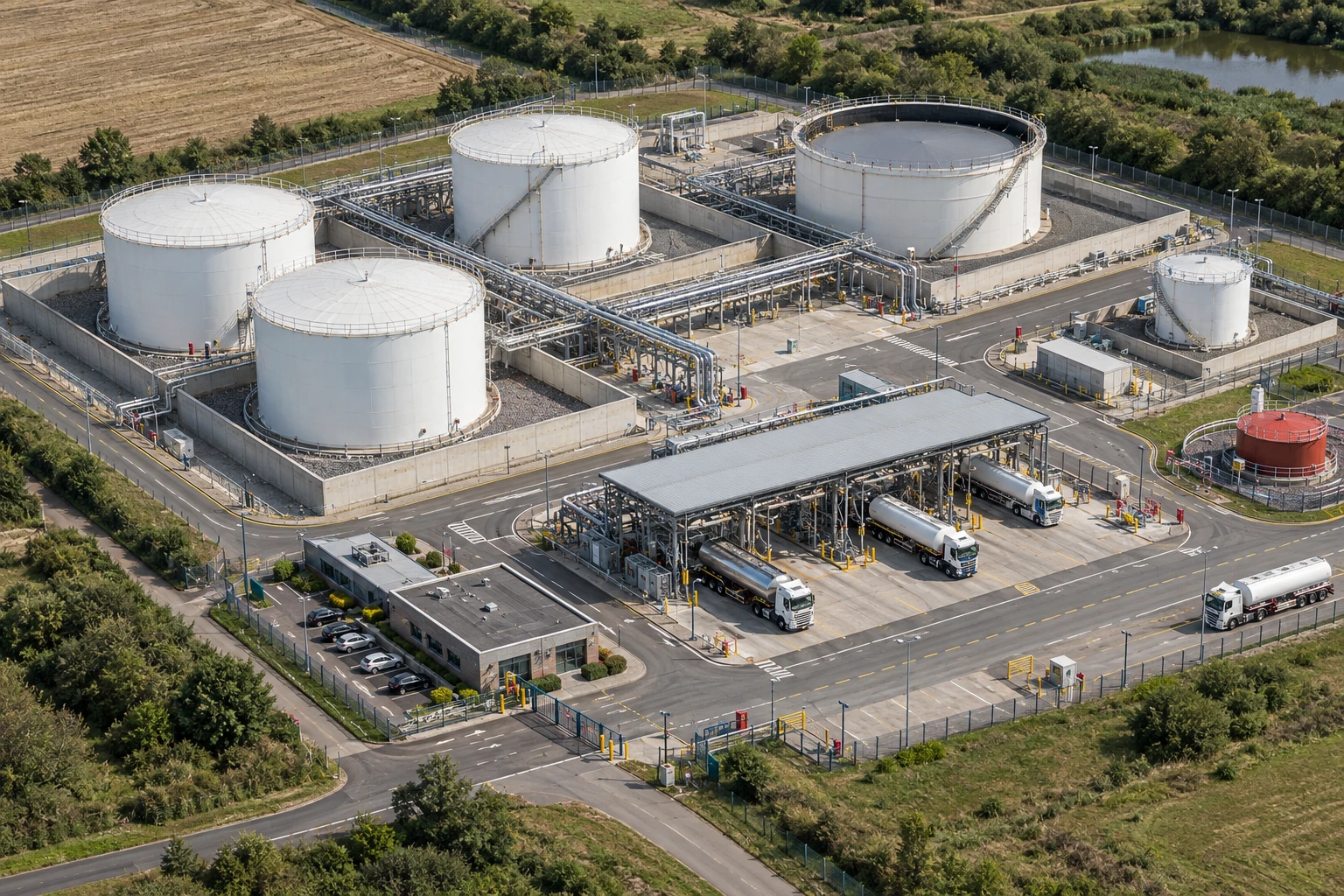
Crownway Fuels Ltd is a fuel terminal with tanks, pumps, pipework, road tanker loading, vapour recovery, electrical systems and contractor maintenance. Isolation failure could cause fire, explosion, toxic exposure, environmental release or fatal injury.
- Assessing — Crownway classifies isolations by substance, pressure, inventory, task intrusiveness and consequence of failure. Isolation standard matrix and risk assessment.
- Planning — Operations and maintenance walk down the system, mark up drawings and agree verification points. Marked P&ID and isolation certificate.
- Implementing — Locks, blinds, drains, vents, gas tests and permits are applied with defined roles. Lock register, blind list and permit pack.
- Training — Authorisers, isolators and acceptors are trained using scenario-based line-breaking exercises. Competence matrix and practical assessment.
- Checking — First-line field checks verify locks and drains; second-line audits sample permit/isolation quality; third-line audits review standards. Assurance findings and action tracker.
- Learning — Any passing valve, unexpected product, gas test failure or permit deviation triggers investigation and standard review. RCA and updated isolation rules.
How does this topic align with ISO 45001?
Use these examples to connect the relevant clauses to your own occupational health and safety management system. For each clause, identify the person responsible, the control in use and the evidence that it works.
Scroll across the table to read all four columns.
| ISO 45001 clause | How it applies | What to put in place | How to verify it works |
|---|---|---|---|
| 8.1.1 Operational planning and control | A line-breaking job depends on controlling all credible paths by which pressure, material or other energy could reach the work point. | Have the responsible engineering and operating staff agree the isolation boundary, who applies it, how its effectiveness is verified and who releases the line for work. Tie reinstatement to confirmation that affected work is complete and people are clear. | Follow one fuel-transfer repair from the equipment and line identifiers through isolation and verification records to the authorised hand-back. |
| 8.1.3 Management of change | A job extension, change of operating state or second maintenance task can invalidate a previously agreed isolation. | Link work packages that share isolations and define how changes are escalated. Before a boundary or shared isolation is changed, reassess the impact and get agreement from the people responsible for affected work. | Sample a shared isolation where one task finished first. Confirm that the protection stayed in effect for the remaining work and both teams understood the handover. |
| 7.2 Competence | Competence to plan, apply or verify an isolation depends on the role and equipment. People need to recognise when they cannot establish or confirm a safe condition. | Define role-specific authorisation and assess people on representative equipment and abnormal cases, such as conflicting line information. Keep authorisation current as roles or equipment change. | Check that the people who signed a sampled isolation held the relevant authorisations at the time. Review a practical assessment that tested how they handle an uncertain condition. |
Selected applications of ISO 45001:2018 with Amendment 1:2024. Use the current standard for a full assessment and check the legal duties that apply to the work and location.
ISO 45001:2018 · 2024 climate action amendment · ISO 45002 implementation guidance · ISO technical committee clause FAQ
What does a fuel-system cutaway reveal about isolation boundaries?
Trace connected tanks, pipes and transfer equipment before considering an isolation plan. An empty-looking space or closed valve symbol does not prove isolation or a gas-free condition.
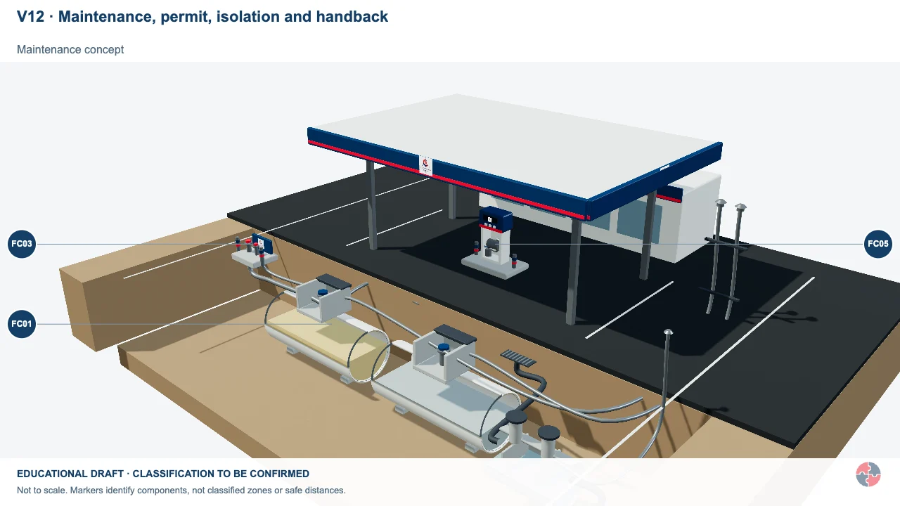
Maintenance, permit, isolation and handback
Maintenance changes the task and may open systems that are closed during normal use.
Activity focus: Inspect the work boundary, nearby live activities and responsibility for restoring the installation.
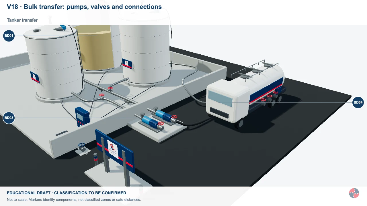
Tanker loading: liquid out, vapour back
Follow petrol from bulk storage into the tanker and the separate displaced-vapour route from the tanker to the terminal VRU.
Activity focus: Distinguish the product line, vapour collection line and tanker-loading protective controls.
Educational illustration, not to scale. Coloured zones are teaching examples, not a site-specific hazardous-area classification.
How can the hierarchy of controls prevent pressure and chemical release during sampling-valve replacement?
Avoid opening a live system where possible. If the work is necessary, identify every energy and material source, apply and verify isolation, remove stored contents and use a controlled first break; stop if the boundary or contents are uncertain.
Stored or connected energy can remain
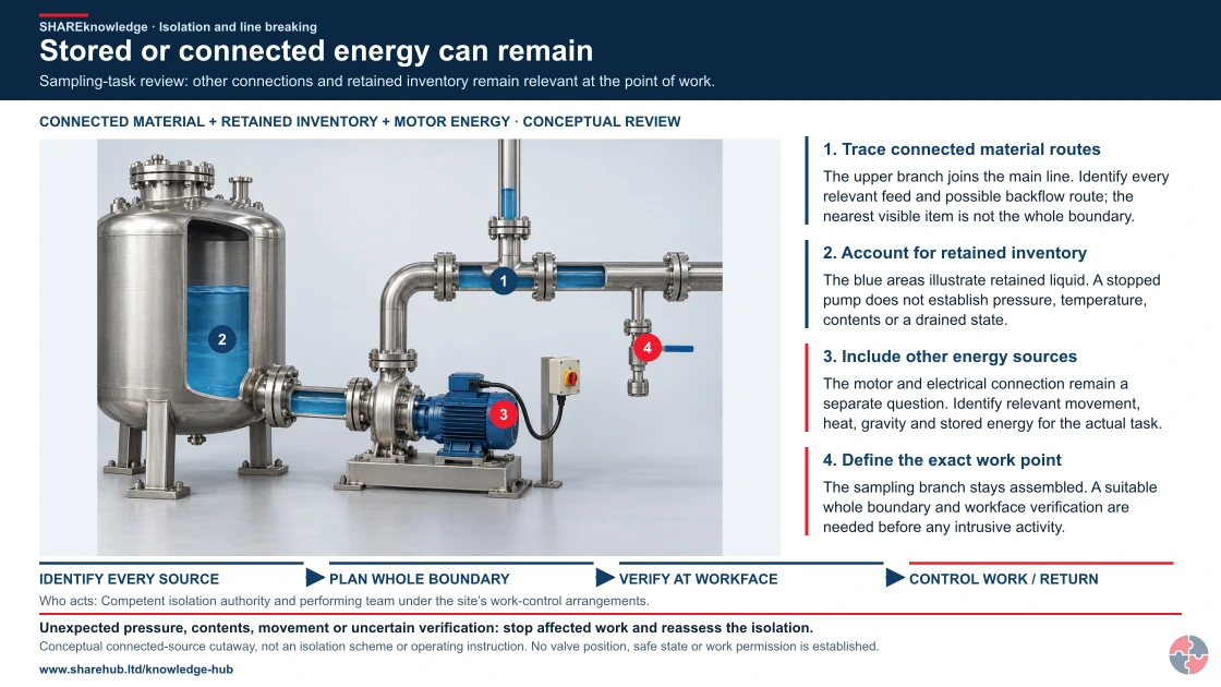
Full written explanation
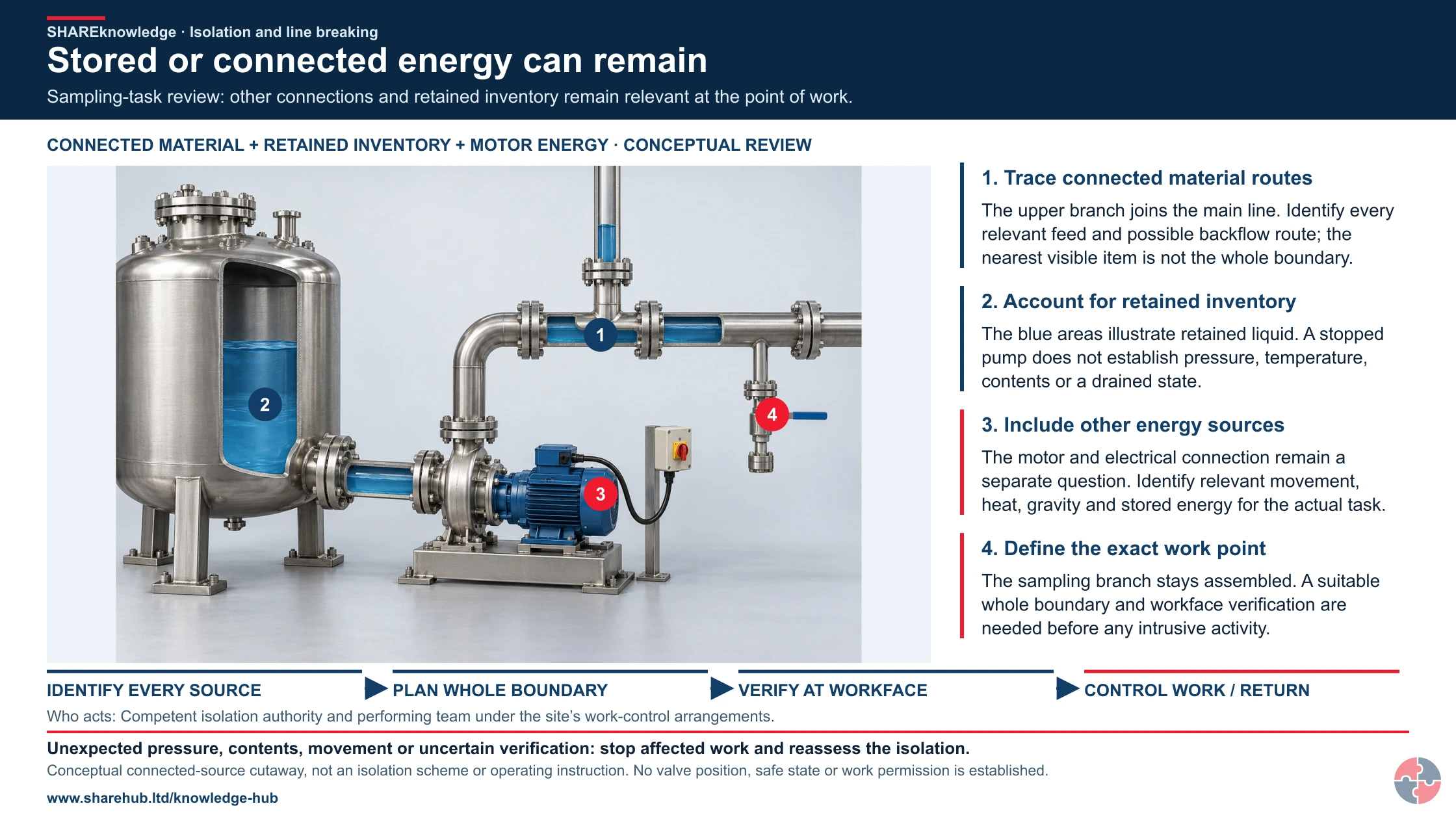
A new realistic equipment cutaway shows a process vessel linked through an intact pump and motor to a main pipe. A second material connection enters through an upper tee, and a small sampling branch remains assembled and capped. Limited cutaway windows show illustrative retained liquid within the vessel and pipe walls. Four native numbered explanations connect those physical features to connected feeds/backflow, stored inventory, separate motor energy and the exact proposed sampling work point. The original pathway remains: relevant energy and material sources can persist; an incorrect, passing or incomplete boundary can fail; intrusive work can release energy, material or movement at the workface. All relevant sources need the actual competent isolation plan and a suitable verification route. This is a conceptual source map, not an engineered or sufficient isolation scheme, valve state, pressure/temperature measurement, drained state, test recipe or permission to open equipment.
Sampling-task review: other connections and retained inventory remain relevant at the point of work.
- Trace connected material routes. The upper branch joins the main line. Identify every relevant feed and possible backflow route; the nearest visible item is not the whole boundary.
- Account for retained inventory. The blue areas illustrate retained liquid. A stopped pump does not establish pressure, temperature, contents or a drained state.
- Include other energy sources. The motor and electrical connection remain a separate question. Identify relevant movement, heat, gravity and stored energy for the actual task.
- Define the exact work point. The sampling branch stays assembled. A suitable whole boundary and workface verification are needed before any intrusive activity.
Change the pathway
- Avoid the intrusive task. Consider methods that do not open a live system.
- Establish the whole boundary. Identify, apply and secure suitable isolations for all relevant sources.
- Verify and maintain. Prove effectiveness at the workface with a defined method and controlled return.
Evidence check: The proving path must itself be suitable and effective; an unreadable or blocked check is not proof.
Use the complete isolation, verification and physical-method explanations
Primary references: HSE HSG253: safe isolation guidance · HSE HSG253: process isolation, proving and monitoring · HSE: competent maintenance and stored energy
Open the complete HD image (new tab)Download image
Use the complete isolation, verification and physical-method explanations
Primary references: HSE HSG253: safe isolation guidance · HSE HSG253: process isolation, proving and monitoring · HSE: competent maintenance and stored energy
| Control priority | Task-specific control and feasibility | Owner, verification, failure and stop point |
|---|---|---|
| Elimination | Use qualified non-intrusive inspection or replace a removable module in a safe workshop if it meets the maintenance purpose; otherwise shut down and remove the hazardous inventory before breaking. | Owner: engineering/operations. Verify inspection capability and isolation scope; stop if the alternative leaves an uninspected safety-critical defect. HSE task guidance |
| Substitution | Where flushing is needed, assess whether a lower-hazard compatible fluid can replace the process chemical and whether reducing pressure/inventory is technically possible. Confirm material compatibility and waste route. | Owner: process engineer. Sample/verify flush and drain; hold the break if residual chemical or pressure remains uncertain. HSE task guidance |
| Engineering | Establish and prove initial process isolation, then safely depressurise/drain/purge the isolated section. Only after zero-energy verification, install a spade or blind by a separate controlled first break where the assessed standard requires positive isolation; prove it before opening the target gasket. A proved double-block-and-bleed alternative needs competent HSG253/site-standard justification. | Owner: competent isolator and independent checker. Verify valve IDs, drain/purge, zero pressure, blind identity and leak integrity at each hold point; stop for wrong line, passing valve, returning pressure or failed atmosphere check. HSG253 isolation sequence |
| Administrative | Coordinate the isolation certificate, permit, marked drawing, simultaneous operations, first-break plan, shift handover and formal reinstatement. Recheck after pause or scope change; paperwork does not make a leaking valve sound. | Owner: area authority/permit issuer. Walk the line and verify signatures and physical state; hold for conflicting work or missing independent check. HSE task guidance |
| Personal protection | Select compatible chemical/thermal gloves, face protection, antistatic clothing and respiratory protection only for the assessed residual splash/vapour route. Check fit, condition, escape and decontamination; PPE cannot contain a major release. | Owner: supervisor/technical specialist. Replace damaged PPE and stop if atmosphere or remaining inventory exceeds the planned protection. HSE task guidance |
How can the ERICPD hierarchy of controls prevent pressure and chemical release during sampling-valve replacement?

| Control level | Control for this activity | Owner and verification | Stop / restart decision |
|---|---|---|---|
| Eliminate | Use a suitable external diagnostic or redesigned sampling arrangement if it removes the intrusive valve task. | Operations and maintenance confirm which fault can be established externally and whether valve removal is genuinely avoided; do not infer pressure or contents from a stopped pump. | If the hazardous step remains, keep it within the task assessment and select the stronger feasible remaining controls. |
| Reduce, including substitution | Use an approved closed sampling system or safely removable module to reduce open access. This is an engineering change; it does not make an unisolated valve safe to remove. | Process engineer confirms closed-system compatibility, safe disconnection, contamination control and the isolation still required for module exchange. | Reject an alternative if its performance is unproved or its new hazards are unresolved. |
| Isolate | Isolate connected feeds and energy sources, remove hazardous contents and verify the defined safe state before breaking containment. | Supervisor checks the actual boundary, affected people and connected work; verify separation or isolation before allowing access. | Hold or stop for unknown contents, pressure, passing isolation or an unapproved change in work scope. |
| Control: physical safeguards | Provide suitable drainage, containment, local extraction and support for the valve and connected pipework. | Competent equipment/process owner checks line identity, isolation points, residual pressure, residue and containment. | Hold or stop for unknown contents, pressure, passing isolation or an unapproved change in work scope. |
| Control: work method and response | Agree the permit, contamination checks, line identification and hand-back with operations and contractors. | Supervisor confirms the work limits, competent cover, communication and stop/restart authority with the people doing this activity. | Hold work when the agreed limits, competent cover or effective communication cannot be maintained. |
| PPE | Specify chemical PPE and any RPE from the actual residue and task assessment; a respirator does not authorise opening an unverified line. | Assessor confirms whether personal protection is needed and checks suitability, condition, compatibility and any required fit evidence. | Do not use unsuitable protection or rely on PPE to continue after an essential source control fails. |
| Discipline | Check assembly, leak testing and restoration of sampling protection before returning the reactor to service. | Release only after operations accepts the leak test and restored sampling arrangement. Retain verification and unresolved restrictions at handover. | Keep the task on hold until required reinstatement evidence and unresolved defects are accepted by the responsible owner. |
How can the ISO 45001 hierarchy of controls prevent pressure and chemical release during sampling-valve replacement?

| Control level | Control for this activity | Owner and verification | Stop / restart decision |
|---|---|---|---|
| Elimination | Use a suitable external diagnostic or redesigned sampling arrangement if it removes the intrusive valve task. | Operations and maintenance confirm which fault can be established externally and whether valve removal is genuinely avoided; do not infer pressure or contents from a stopped pump. | If the hazardous step remains, keep it within the task assessment and select the stronger feasible remaining controls. |
| Engineering controls | Use an approved closed sampling system or safely removable module to reduce open access. This is an engineering change; it does not make an unisolated valve safe to remove. | Process engineer confirms closed-system compatibility, safe disconnection, contamination control and the isolation still required for module exchange. | Reject an alternative if its performance is unproved or its new hazards are unresolved. |
| Engineering controls | Isolate connected feeds and energy sources, remove hazardous contents and verify the defined safe state before breaking containment. | Supervisor checks the actual boundary, affected people and connected work; verify separation or isolation before allowing access. | Hold or stop for unknown contents, pressure, passing isolation or an unapproved change in work scope. |
| Engineering controls | Provide suitable drainage, containment, local extraction and support for the valve and connected pipework. | Competent equipment/process owner checks line identity, isolation points, residual pressure, residue and containment. | Hold or stop for unknown contents, pressure, passing isolation or an unapproved change in work scope. |
| Administrative controls | Agree the permit, contamination checks, line identification and hand-back with operations and contractors. | Supervisor confirms the work limits, competent cover, communication and stop/restart authority with the people doing this activity. | Hold work when the agreed limits, competent cover or effective communication cannot be maintained. |
| PPE | Specify chemical PPE and any RPE from the actual residue and task assessment; a respirator does not authorise opening an unverified line. | Assessor confirms whether personal protection is needed and checks suitability, condition, compatibility and any required fit evidence. | Do not use unsuitable protection or rely on PPE to continue after an essential source control fails. |
| Administrative controls | Check assembly, leak testing and restoration of sampling protection before returning the reactor to service. | Release only after operations accepts the leak test and restored sampling arrangement. Retain verification and unresolved restrictions at handover. | Keep the task on hold until required reinstatement evidence and unresolved defects are accepted by the responsible owner. |
What training supports isolation competence?
Isolation competence must be demonstrated on the actual plant and energy sources, including independent verification and safe handback; permit training alone is insufficient.
Operators and maintainers need assessed practice in line identification, isolation points, lock control, draining, venting and test-before-touch. Permit issuers must challenge drawings against the real plant and coordinate simultaneous operations. A supervisor should observe a complete hold, verification and handback; repeat assessment after modified pipework, an isolation failure or a new contractor interface.
| Role | Learning and decision | Demonstration and assessor | Record and reassessment trigger |
|---|---|---|---|
| Operator or isolator | Identify all energy paths, apply locks, drain/vent and verify at the point of work. | Second competent person observes a real isolation. | Isolation certificate and lock register; reassess after plant change. |
| Maintainer or contractor | Confirm equipment identity, first-break method and stop route. | Permit issuer tests a practical line-break briefing. | Authorisation and first-break record; refresh after task change. |
| Permit issuer or area authority | Reconcile permit, isolation certificate, SIMOPS and handback. | Manager audits a live hold/restart decision. | Permit and independent verification; revisit after deviation. |
| Engineer or process safety adviser | Select isolation standard and assess credible loss-of-containment consequences. | Technical peer challenges barrier design. | Isolation design basis and review; revisit after MOC or incident. |
How should management check and improve these controls?
HSE’s Plan, Do, Check, Act approach helps an organisation plan controls, put them into use, check performance and correct failures. It is management guidance, not a substitute for the GB or Northern Ireland legal duties that apply to the task.
Assign an isolation owner, verify the boundary and stored-energy release, and record the hand-back. Investigate any failed prove-dead or positive-isolation check before restarting. HSE management guidance
How should PSM learners use this page?
Strong PSM answers connect HSG253, isolation standards, verification, permits, SIMOPS, handback and barrier assurance.
A strong process-safety answer connects the credible release to an isolation standard, physical proof, permit coordination and controlled reinstatement. Explain why a signed permit alone cannot establish the line is safe.
- Explain safe isolation — Energy inventory, physical isolation, lockout, verification and handback. Switch it off.
- Discuss line breaking — Contents, pressure, drains, PPE, line of fire, gas testing and stop criteria. Open the flange carefully.
- Explain HSG253 thinking — Risk-based baseline standard, consequence, valve integrity and positive isolation. Use two valves.
- Connect permits — Permit controls work; isolation certificate records isolation and verification evidence. Permit means safe.
- Discuss assurance — Field verification, audits, passing-valve learning and action close-out. Keep forms.
What warning signs show isolation control is weak?
Warning signs include paperwork-first permits, unverified isolations, scope creep and weak handback.
A passing valve, unexpected pressure, wrong tag or unaccounted connected line is a hold point, not a paperwork discrepancy. Keep the system contained, inform the isolation owner and reverify the boundary and zero-energy condition before any further break.
- Permit issued from office — Field verification may be weak. Require walkdown and point-of-work check.
- Tags but no locks — Physical control may be absent. Review LOTO standard.
- No drain/vent evidence — Stored pressure or product may remain. Stop and verify zero energy.
- Workers cannot explain isolation boundary — Briefing or certificate is weak. Rebrief and mark up drawing.
- Scope changes mid-job — Isolation may no longer match task. Suspend and reauthorise.
- Leaks at restart — Handback/reinstatement weakness. Improve leak test and reinstatement checks.
What do the acronyms and key terms mean?
These terms explain the decisions used in this page.
| Acronym | Meaning | Plain-English use |
|---|---|---|
| HSG253 | Safe isolation of plant and equipment | HSE guidance on process isolation. |
| LOTO | Lockout/Tagout | Locking and tagging isolation points to prevent operation. |
| PTW | Permit to Work | Formal authorisation system for high-risk work. |
| SIMOPS | Simultaneous Operations | Concurrent activities that can interact. |
| DBB | Double Block and Bleed | Isolation method using two valves and a bleed point. |
| P&ID | Piping and Instrumentation Diagram | Drawing showing process equipment, lines and instrumentation. |
Which BuildOut documents support this topic?
Download individual editable BuildOut documents for this topic. Procedures and plans contain completed arrangements; forms, checklists, assessments, RAMS and permits are blank masters. Registers include separate worked examples.
| Document | Purpose and content | Editable download |
|---|---|---|
| Electrical installation, safe isolation and tool inspection procedure BOUK-PRO-ELEC · Completed worked example · v1.0 | Plan temporary distribution, verify installation integrity, control energisation and prevent unauthorised work. | Download DOCX Read preview |
| Temporary electrical installation and distribution plan BOUK-PLN-ELEC-01 · Completed worked example · v1.0 | Define suitable supply, protection, cable routes, checks and controlled alterations. | Download DOCX Read preview |
| Electrical isolation and re-energisation permit BOUK-PTW-ELEC-01 · Blank editable master · v1.0 | Identify isolation points, prove dead, lock off and control reinstatement. | Download DOCX Read preview |
| Electrical tools, leads and distribution inspection BOUK-CHK-ELEC-01 · Blank editable master · v1.0 | Set risk-based user checks and inspection/testing arrangements. | Download DOCX Read preview |
| Overhead-line and live-service proximity assessment BOUK-RA-ELEC-01 · Blank editable master · v1.0 | Plan avoidance, exclusion, utility coordination and safe work methods. | Download DOCX Read preview |
| Electrical installation verification and defect closeout BOUK-FRM-ELEC-01 · Blank editable master · v1.0 | Retain competent test/verification and restoration evidence. | Download DOCX Read preview |
| Permit issue, suspension, handover and cancellation procedure BOUK-PRO-PTW · Completed worked example · v1.0 | Identify permit interfaces, competence, isolations, simultaneous operations and restoration. | Download DOCX Read preview |
| Permit register and simultaneous-operations board BOUK-REG-PTW-01 · Blank register with separate worked entries · v1.0 | Coordinate active permits, isolations, interfaces and shift handovers. | Download XLSX Read preview |
| General high-risk work permit BOUK-PTW-PTW-01 · Blank editable master · v1.0 | Document work boundary, prerequisites, controls, time validity and accountable release. | Download DOCX Read preview |
| Isolation certificate and lock register BOUK-FRM-PTW-01 · Blank editable master · v1.0 | Record energy source, isolation point, lock owner, verification and restoration. | Download DOCX Read preview |
| Permit suspension, handover and cancellation record BOUK-FRM-PTW-02 · Blank editable master · v1.0 | Control temporary stop, personnel/shift change and final safe handback. | Download DOCX Read preview |
| Permit-system audit and field verification BOUK-CHK-PTW-01 · Blank editable master · v1.0 | Test whether permits match actual site conditions and controls. | Download DOCX Read preview |
| Electrical first/second fix and commissioning RAMS BOUK-RAMS-ELEC-01 · Blank editable master · v1.0 | Safe isolation, competence, temporary power, access and controlled energisation. | Download DOCX Read preview |
Review and adapt the documents for your organisation, activities and jurisdiction before approval and issue. Open the SHAREms management-system hierarchy to find each document under its parent policy.
Which Crownway Fuels documents support this topic?
Open an editable document, read the preview, or find its place in the Crownway hierarchy. 7 resources relate to this page.
Fictional Crownway Fuels examples for English forecourts, with a separate illustrative bulk terminal. Check site applicability, permissions and actual controls before adapting any document for use.
Isolation breaking containment and return to service policy (7)
- Isolation breaking containment and return to service policy (CWF-POL-ISO · Completed fictional example)
Set company expectations, responsibilities and resources for isolation breaking containment and return to service.
Read preview · Download DOCX · Show in hierarchy - Isolation breaking containment and return to service procedure (CWF-PRO-ISO · Completed fictional example)
Explain who does what, in what sequence, the control rationale, evidence, escalation and safe restart conditions.
Read preview · Download DOCX · Show in hierarchy - Equipment isolation and lockout schedule (CWF-PLN-ISO-01 · Completed fictional example)
Provide the site/task-specific equipment isolation and lockout schedule and retain its controlled output.
Read preview · Download DOCX · Show in hierarchy - Breaking containment and line opening permit (CWF-PTW-ISO-01 · Blank editable master)
Provide the site/task-specific breaking containment and line opening permit and retain its controlled output.
Read preview · Download DOCX · Show in hierarchy - Electrical and mechanical isolation proof check (CWF-CHK-ISO-01 · Blank editable master)
Provide the site/task-specific electrical and mechanical isolation proof check and retain its controlled output.
Read preview · Download DOCX · Download PDF · Show in hierarchy - Group isolation and shift handover certificate (CWF-FRM-ISO-01 · Blank editable master)
Provide the site/task-specific group isolation and shift handover certificate and retain its controlled output.
Read preview · Download DOCX · Show in hierarchy - Deisolation and return to service approval (CWF-CHK-ISO-02 · Blank editable master)
Provide the site/task-specific deisolation and return to service approval and retain its controlled output.
Read preview · Download DOCX · Download PDF · Show in hierarchy
Unlock another resource
You have used this month’s two free downloads. Publish a post in your own words to unlock one more resource, or choose SHARE Individual for 10 downloads per month.
You decide whether to share. If you do, use the relevant platform disclosure tools and do not make claims you do not genuinely hold.