SHARE Knowledge Hub
Flammability Limits and Vapour Cloud Behaviour
Flammability limits describe potential to ignite under defined conditions, not an all-clear in the field. Assess credible vapour-cloud release, dispersion, ignition and explosion scenarios; verify barriers and detector response. Apply GB or NI DSEAR according to location.
Understanding Flammability Limits and Vapour Cloud Behaviour
Flammability limits describe potential to ignite under defined conditions, not an all-clear in the field. Assess credible vapour-cloud release, dispersion, ignition and explosion scenarios; verify barriers and detector response. Apply GB or NI DSEAR according to location.
Why this matters at work
Use the actual credible scenario to distinguish rapid flame travel, pressure effects and escalation rather than equate every flammable cloud with the same explosion. The HSE Buncefield page is a current gateway to historic investigation and research; its overview cannot replace reading a specific archived model. Preserve layout and barrier dependencies for competent analysis. Buildings, temporary structures and occupancy changes can invalidate the previous scenario basis.
Reject fan-running and healthy detector indications as proof of a changed enclosure. Review actual source, geometry, occupied areas, ventilation and shared dependencies. Verify complete functions and test exclusions, inform affected shifts, retain restrictions and reopen/correct/safely retest failures. Technical restoration and operating permission remain separate.
How organisations manage this in practice
Review such changes before introducing dangerous substances or ignition sources. Identify how vapour enters, accumulates or escapes, which people and equipment are exposed and whether detection and emergency routes remain effective. Prefer avoiding the release or incompatible simultaneous work to relying solely on added monitoring. Competent process or explosion assessment may be needed for consequential uncertainty; do not invent an exclusion radius or pressure prediction from a sketch. Record the temporary design, duration, inspection and stop conditions, with a responsible owner. Remove temporary arrangements through controlled handback and verify that ventilation, access and protective functions have actually returned to the intended state.
A competent design should connect an alarm to an achievable response, such as safe task stoppage or engineered shutdown, and assess utilities and human dependencies. Set thresholds from the scenario and applicable technical basis rather than copying a percentage from another site. Check commissioning, suitable functional tests, calibration and impairment control against instructions and risk. Brief workers on alarms, faults and limitations, including when to withdraw. Record assumptions, acceptance criteria and who reviews changes in material, layout or operating conditions. Detection supplements prevention and containment; it cannot make an uncontrolled flammable cloud safe, establish health protection by itself or replace a separate work-authorisation system.
A rich release can mix with surrounding air and pass through flammable concentrations at its edges or as it disperses. A sample taken at one point may miss those regions. Composition can also change during ventilation, draining or opening equipment. Describing the bulk atmosphere as too rich therefore does not eliminate the risk of ignition elsewhere or later. Avoid release where practicable and assess the whole pathway, including ventilation failure, pockets, drains and connected spaces. Do not deliberately admit air or open equipment on the assumption that dilution is automatically safe. Isolation, purging, atmospheric testing and work permission need a competent task-specific method and defined acceptance criteria. Ensure instruments are suitable for the substance, oxygen conditions and measurement range, with understood failure or overrange behaviour. Keep toxic and oxygen-deficiency hazards in the assessment. Record locations, timing, limitations and stop conditions. An apparently reassuring sample cannot authorise hot work or entry into an unexamined system, and this explanation supplies no universal dilution or purging procedure.
How can I practise this topic in 3D?
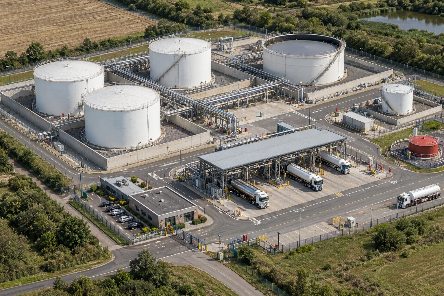

The planned receipt has not established safe ullage
All related inspection points 6 across 1 location
Crown Fuels terminal 6 inspection points
Practice in the SHAREhub environment. Browser practice is separate from workplace competence and formal learning records.
Follow the cloud pathway and the limits of the measurement
Compare a petrol spill spreading across a loading surface with an LPG release collecting through low-level pathways. The actual release, ventilation, terrain, drains, obstructions and ignition sources determine the exposure and detector coverage. One low reading at a distant sensor does not establish conditions where the material is accumulating.
A spill edge is not the edge of a possible vapour hazard
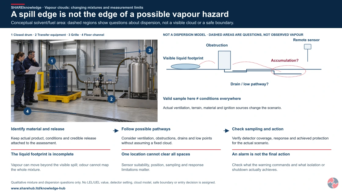
Full written explanation
An illustrative intact solvent-transfer scene shows a closed drum, connected transfer equipment, a grille and floor channel. Picture key: 1 Closed drum · 2 Transfer equipment · 3 Grille · 4 Floor channel. The scene does not show a spill, gas, a verified drainage connection or detector coverage. Beside it, a separate conceptual map distinguishes a possible visible liquid footprint, obstruction and low pathway from a possible accumulation question and a remote sensing position. Dashed regions and paths are questions, not observed vapour, measured dispersion, a fixed hazardous-area boundary or a safe approach route. A valid local sample does not describe conditions everywhere. Actual ventilation, terrain, material and ignition sources change the scenario. Three paired explanations identify material and release, follow possible pathways, then check sampling and achieved protection. No release condition, concentration, sensor placement, ventilation adequacy, cloud extent or entry permission is established by the scene.
Conceptual solvent/fuel area: dashed regions show questions about dispersion, not a visible cloud or a safe boundary.
- Identify material and release. Keep actual product, conditions and credible release attached to the assessment.
- Follow possible pathways. Consider ventilation, obstructions, drains and low points without assuming a fixed cloud.
- Check sampling and action. Verify detector coverage, response and achieved protection for the actual scenario.
Change the pathway
- The liquid footprint is incomplete. Vapour can move beyond the visible spill; odour cannot map the whole mixture.
- One location cannot clear all spaces. Sensor suitability, position, sampling and response limitations matter.
- An alarm is not the final action. Check what the warning commands and what isolation or shutdown actually achieves.
Evidence check: Qualitative mixture and dispersion questions only. No LEL/UEL value, detector setting, cloud model, safe boundary or entry decision is assigned.
Read material conditions, detector limitations and achieved protective action
Primary references: HSE flammable-liquid handling publication scope, 2015 · HSE leak/gas detection: purpose, coverage and response
Open the complete HD image (new tab)Download image
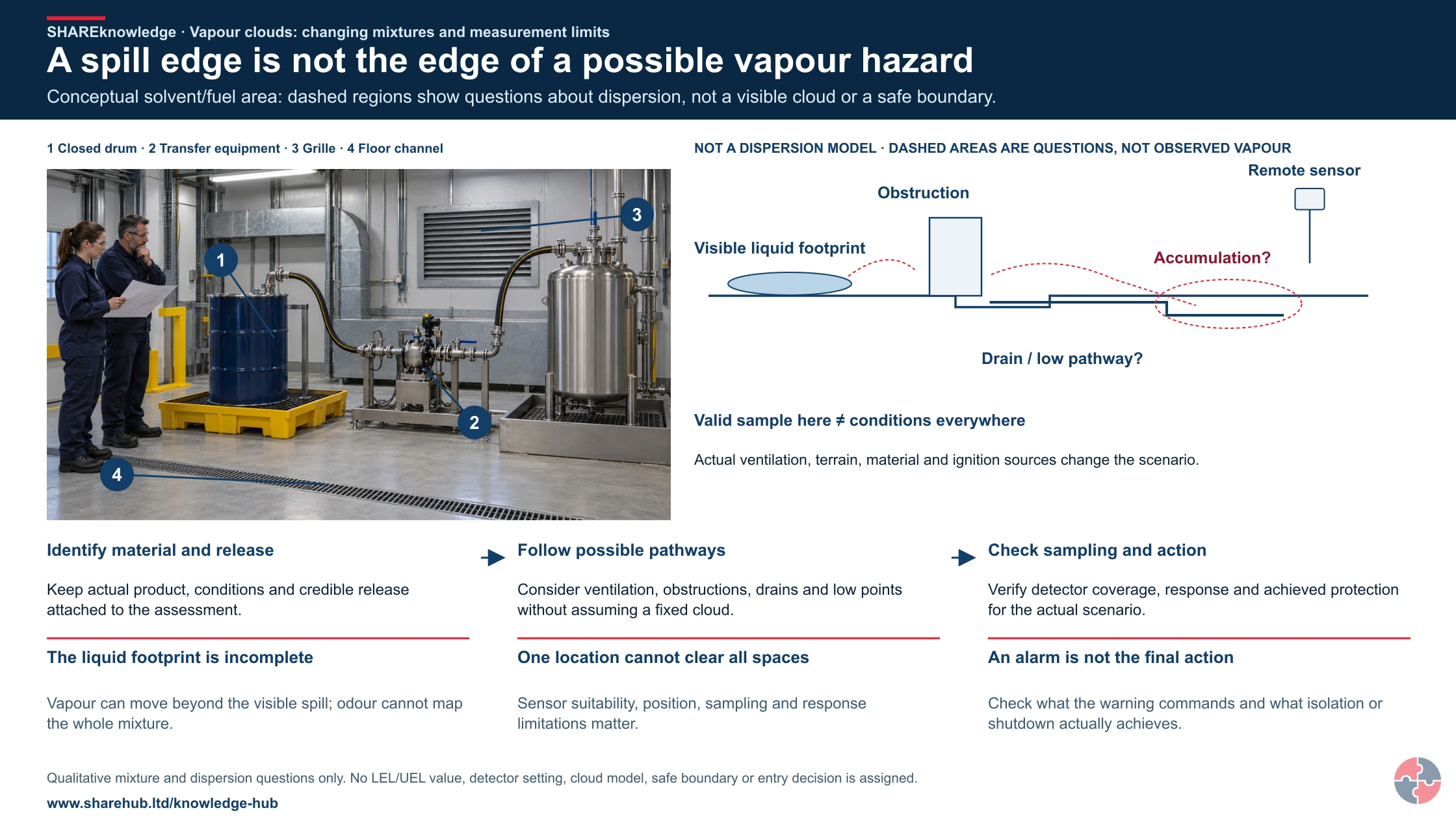
Read material conditions, detector limitations and achieved protective action
Primary references: HSE flammable-liquid handling publication scope, 2015 · HSE leak/gas detection: purpose, coverage and response
Best-practice guide: Flammability Limits and Vapour Cloud Behaviour
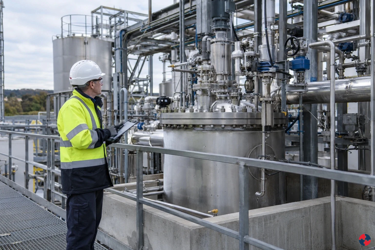
Follow the cloud pathway and the limits of the measurement
Compare a petrol spill spreading across a loading surface with an LPG release collecting through low-level pathways. The actual release, ventilation, terrain, drains, obstructions and ignition sources determine the exposure and detector coverage. Flammability limits describe potential to ignite under defined conditions, not an all-clear in the field.
Turn flammability limits and vapour cloud behaviour knowledge into a decision
Flammability limits describe potential to ignite under defined conditions, not an all-clear in the field. Assess credible vapour-cloud release, dispersion, ignition and explosion scenarios; verify barriers and detector response. Overfill prevention and independent high-level protection are vapour cloud controls.
Three questions about a release
Release source: Identify the actual substance, release conditions and prevention arrangements. Mixing and connected space: Assess possible variation, accumulation and unmeasured pockets without treating the sketch as fixed zones. Measurement limitation: A reading at one place and time cannot describe every part of the mixture or provide automatic entry permission.
Warning signs and how harm could develop
Repeated small leaks: A larger release may be normalised until it forms a flammable cloud. Gas detectors frequently bypassed: Detection barrier may be unavailable during a release. Generic hot-work permits: Ignition sources may be introduced without understanding vapour pathways.
Choose controls for the actual task
Elimination: Avoid the transfer until storage capacity and safe receiving route are proven. Substitution: Reduce dangerous inventory or select a safer transfer method where technically feasible. Engineering: Use independent high-level protection, closed transfer, containment and isolation. Administrative: Set transfer limits, line-up verification and alarm response with stop authority. PPE: Use suitable PPE for residual task exposure; it cannot prevent a vapour-cloud explosion. Read the full control table for qualifications, ownership and verification. Use the actual task and applicable jurisdiction; existing technical approval remains unchanged.
Use the full flammability limits and vapour cloud behaviour lesson
Use the full topic for the decision points, practical examples, detailed control tables and source scope. HSE guidance applies to Great Britain; use HSENI for the Northern Ireland route and the source’s stated jurisdiction. A simplified guide does not change the page’s technical-review or approval status.

Read all six steps as text
1. Follow the cloud pathway and the limits of the measurement
Compare a petrol spill spreading across a loading surface with an LPG release collecting through low-level pathways.
- Avoid / redesign: Avoid the transfer until storage capacity and safe receiving route are proven.
- Control the task: Use independent high-level protection, closed transfer, containment and isolation.
- Verify before release: Capacity or route uncertain: do not start.
Compare a petrol spill spreading across a loading surface with an LPG release collecting through low-level pathways. The actual release, ventilation, terrain, drains, obstructions and ignition sources determine the exposure and detector coverage. Flammability limits describe potential to ignite under defined conditions, not an all-clear in the field.
Apply it: Which part of this plan would you check at the workface before authorising the task?
2. Turn flammability limits and vapour cloud behaviour knowledge into a decision
Use the evidence to improve the actual work arrangement.
- Change at source: Avoid the transfer until storage capacity and safe receiving route are proven.
- Make it observable: Capacity or route uncertain: do not start.
- Keep useful evidence: Overfill prevention and independent high-level protection are vapour cloud controls.
Flammability limits describe potential to ignite under defined conditions, not an all-clear in the field. Assess credible vapour-cloud release, dispersion, ignition and explosion scenarios; verify barriers and detector response. Overfill prevention and independent high-level protection are vapour cloud controls.
Apply it: What evidence would show that the change improves this task, rather than only completing a record?
3. Three questions about a release
Example: a practical application of the existing topic lesson.
- Release source: Identify the actual substance, release conditions and prevention arrangements.
- Mixing and connected space: Assess possible variation, accumulation and unmeasured pockets without treating the sketch as fixed zones.
- Measurement limitation: A reading at one place and time cannot describe every part of the mixture or provide automatic entry permission.
Release source: Identify the actual substance, release conditions and prevention arrangements. Mixing and connected space: Assess possible variation, accumulation and unmeasured pockets without treating the sketch as fixed zones. Measurement limitation: A reading at one place and time cannot describe every part of the mixture or provide automatic entry permission.
Apply it: At which point would you hold this example, and what evidence would allow it to proceed?
4. Warning signs and how harm could develop
Connect the task, the route to the person and the control that can fail.
- Repeated small leaks: A larger release may be normalised until it forms a flammable cloud.
- Gas detectors frequently bypassed: Detection barrier may be unavailable during a release.
- Generic hot-work permits: Ignition sources may be introduced without understanding vapour pathways.
Repeated small leaks: A larger release may be normalised until it forms a flammable cloud. Gas detectors frequently bypassed: Detection barrier may be unavailable during a release. Generic hot-work permits: Ignition sources may be introduced without understanding vapour pathways.
Apply it: Who could be exposed, including other trades, cleaners, maintainers and people nearby?
5. Choose controls for the actual task
Control summary. Read the complete task-specific controls and checks in the linked topic.
- Elimination: Avoid the transfer until storage capacity and safe receiving route are proven.
- Substitution: Reduce dangerous inventory or select a safer transfer method where technically feasible.
- Engineering controls: Use independent high-level protection, closed transfer, containment and isolation.
- Administrative controls: Set transfer limits, line-up verification and alarm response with stop authority.
- PPE: Use suitable PPE for residual task exposure; it cannot prevent a vapour-cloud explosion.
Elimination: Avoid the transfer until storage capacity and safe receiving route are proven. Substitution: Reduce dangerous inventory or select a safer transfer method where technically feasible. Engineering: Use independent high-level protection, closed transfer, containment and isolation. Administrative: Set transfer limits, line-up verification and alarm response with stop authority. PPE: Use suitable PPE for residual task exposure; it cannot prevent a vapour-cloud explosion. Read the full control table for qualifications, ownership and verification. Use the actual task and applicable jurisdiction; existing technical approval remains unchanged.
Apply it: Which stronger option can be used here, and who will verify it before accepting the remaining risk?
6. Use the full flammability limits and vapour cloud behaviour lesson
Follow the official sources below and retain the task-specific evidence.
- Official guidance: HSE DSEAR background
- Official guidance: HSE HSG140
- Task decision: An apparently reassuring point does not release the whole area. Use the assessed controls and competent decision; no numerical entry permission is supplied here.
Use the full topic for the decision points, practical examples, detailed control tables and source scope. HSE guidance applies to Great Britain; use HSENI for the Northern Ireland route and the source’s stated jurisdiction. A simplified guide does not change the page’s technical-review or approval status.
Apply it: Which official source and full-topic section will you use to resolve the next decision?
Keep the substance, calibration basis, units, sampling position and response attached to any detector reading. LEL and UEL describe flammability under defined conditions, not a general safe-entry permission. Where coverage, instrument suitability or response is uncertain, stop the affected task and use the assessed emergency and isolation arrangements. Do not improvise a universal percentage threshold to justify continuing.
Two releases escape the coverage assumption
Illustrative example. A petrol spill follows a drain route while an LPG leak can collect at a low point not represented by the nearest detector.
Decision. The competent team reviews both pathways and holds affected operations until suitable coverage and response are established.
Evidence to check. Substance/release information, site geometry, instrument basis and locations, and verified isolation/response arrangements.
Hold or escalation point. Do not use a low remote reading as an all-clear for the actual cloud or entry location.
Follow-up. Review detection and release prevention after layout, product, ventilation or operating changes.
A local reading cannot describe every part of a mixture
Flammable mixtures can vary with location and time. Qualitative rich, flammable and lean regions are not fixed zones or safe-entry boundaries.

Identify the release
Use the actual substance, release conditions, containment and ventilation assessment.
Expect variation
Mixing, obstructions and connected spaces can leave unmeasured pockets; behaviour is substance- and condition-dependent.
Interpret measurements competently
Record where, when, what and how measurements were taken, including instrument limits and missing coverage.
Hold uncertainty
An apparently reassuring point does not release the whole area. Use the assessed controls and competent decision; no numerical entry permission is supplied here.
Read the complete task-specific control examples
ERICPD is a planning cross-map: Discipline verifies and sustains every control. ESEAP compares effectiveness. A label does not authorise the task; retain the owner, evidence and stop or change decision.
Flammability Limits and Vapour Cloud Behaviour · ERICPD
- Eliminate
- Avoid the transfer until storage capacity and safe receiving route are proven.
- Reduce
- Reduce dangerous inventory or select a safer transfer method where technically feasible.
- Isolate
- Use independent high-level protection, closed transfer, containment and isolation.
- Control
- Set transfer limits, line-up verification and alarm response with stop authority.
- PPE
- Use suitable PPE for residual task exposure; it cannot prevent a vapour-cloud explosion.
- Discipline
- Trend overfill signals, bypasses and proof-test failures; verify closed actions.
Flammability Limits and Vapour Cloud Behaviour · ESEAP
- Elimination
- Avoid the transfer until storage capacity and safe receiving route are proven.
- Substitution
- Reduce dangerous inventory or select a safer transfer method where technically feasible.
- Engineering controls
- Use independent high-level protection, closed transfer, containment and isolation.
- Administrative controls
- Set transfer limits, line-up verification and alarm response with stop authority.
- PPE
- Use suitable PPE for residual task exposure; it cannot prevent a vapour-cloud explosion.
What are the key points for flammability limits and vapour cloud behaviour?
LEL and UEL describe a laboratory flammability range; they cannot by themselves prove that a release, workplace or detector reading is safe. Assess the credible release, mixing, ignition, escalation and barrier condition at the actual site.
LEL and UEL define the ignitable range
A mixture below the lower limit is too lean; a mixture above the upper limit is too rich, but dilution can bring it back into the dangerous range.
Vapour clouds are dynamic
Cloud size and movement depend on release rate, pressure, temperature, evaporation, vapour density, ventilation, weather, drains, bunds and terrain.
Explosion severity depends on surroundings
Congestion and confinement can increase turbulence, flame speed and overpressure, so an apparently open site can still have damaging explosion potential.
Detection is not prevention
Gas detectors can provide early warning, but only if they are selected, positioned, maintained and linked to effective response actions.
DSEAR is the main UK workplace frame
DSEAR turns the science into duties: assess dangerous substances, prevent explosive atmospheres, control ignition and reduce consequences.
Major accident learning matters
Buncefield and Texas City show how routine operations, weak signals and poor barrier assurance can produce catastrophic vapour cloud events.
For the legal prevention and mitigation order see HSE DSEAR in detail for Great Britain and HSENI L138 for the Northern Ireland 2003 regime.
What do flammability limits and vapour cloud behaviour mean?
They describe whether a released material can burn or explode, how the cloud forms and how the surrounding environment changes the consequence.
A dispersing flammable cloud can cause a flash fire or, where conditions favour pressure generation, a vapour-cloud explosion after delayed ignition. A jet fire instead follows ignition of a continuing pressurised release; a pool fire follows ignition of a liquid pool. The initiating release and fuel configuration determine which scenario to assess.
For a learner, the subject has three layers. First, the chemical and physical properties: LEL, UEL, flash point, vapour pressure, autoignition temperature and vapour density. Second, the release behaviour: pressure, hole size, liquid spill, evaporation, ventilation, drainage and weather. Third, the management controls: containment, detection, isolation, hazardous area classification, ignition control, emergency response and assurance evidence.
| Concept | Plain-English meaning | Practical question |
|---|---|---|
| Lower explosive limit | The lowest concentration in air that can ignite. | Could a leak or spill create vapour above the lower limit? |
| Upper explosive limit | The highest concentration in air that can still propagate flame. | Could dilution or ventilation move a rich cloud back into the flammable range? |
| Flash point | The lowest temperature at which a liquid gives off enough vapour to ignite under test conditions. | Could the liquid be warm, sprayed, misted or exposed in a way that changes risk? |
| Autoignition temperature | The temperature at which a substance can ignite without a spark or flame. | Are hot surfaces, heaters, engines or process equipment hot enough to ignite vapour? |
| Vapour density | Whether vapour is heavier or lighter than air. | Could vapour collect in pits, bunds, drains, low areas or enclosed spaces? |
| Vapour cloud explosion | Explosion after delayed ignition of a flammable cloud. | Could a release travel before ignition and involve a larger area than the leak point? |
How should LEL and UEL be understood?
LEL/LFL is the lower flammable concentration and UEL/UFL the upper concentration under defined test conditions. A concentration below a detector alarm or above the UEL at one point does not establish a safe area: mixing, dilution and sensor location can create flammable pockets.
The lower explosive limit is often the first number people remember, but it should not be used in isolation. A detector reading below LEL does not automatically prove the whole area is safe, because concentration can vary across a cloud and a detector only measures where it is located. Equally, a mixture above the upper limit can become flammable as it mixes with fresh air.
Gas detection alarms are commonly set as a percentage of LEL, so workers must understand what the alarm means. A low alarm may require stopping work, withdrawal or trained investigation from a safe location under the verified response plan; it does not authorise entry into a suspected cloud. A high alarm may mean immediate evacuation or emergency shutdown. The exact response should be defined in the site's procedures.
| Condition | Meaning | Control implication |
|---|---|---|
| Below LEL | Too little fuel in air to propagate flame at that point. | Do not assume the whole area is safe; cloud concentration can vary. |
| From LEL through UEL under stated test conditions | The mixture is within its flammable range under those conditions. | Stop work, control ignition, investigate, isolate and follow alarm response. |
| Between LEL and UEL | The mixture can ignite and flame can propagate. | Prevent ignition and remove people from the affected area. |
| Above UEL | Too much fuel and too little oxygen at that point. | Dilution can bring the cloud back through the flammable range, so treat as dangerous. |
| Percentage of LEL | Detector alarm scale showing how close the measured concentration is to the LEL. | Alarm setpoints must be understood, maintained and linked to action. |
| Local pockets | Different parts of the cloud may have different concentrations. | Detector placement, ventilation and area control matter. |
The published limits depend on test conditions and can shift with gas mixture, oxygen concentration, temperature and pressure. Use validated substance/process data; do not transfer one table value to an oxygen-enriched, heated or mixed atmosphere without competent analysis.
HSE explains flammable limits in its DSEAR background: HSE DSEAR background.
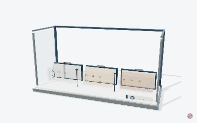
How do flammable limits change across a vapour cloud?
A local fuel-air mixture may be too lean, in a flammable range or too rich for flame to propagate under stated conditions. A rich cloud can have a flammable edge where it mixes with air.
Read the complete lesson without the viewer
A rich cloud core grades through an illustrative flammable edge toward a lean region beside a non-numeric LEL-to-UEL concept band.
FS08 · The flammable range is a local condition
A local fuel-air mixture may be too lean, in a flammable range or too rich for flame to propagate under stated conditions. A rich cloud can have a flammable edge where it mixes with air.
LEL and UEL, also called LFL and UFL, describe flame propagation for a specified mixture and test basis. They are not an explosion-severity prediction. The limits and actual distribution depend on the substance and conditions. A locally rich atmosphere can become ignitable during mixing; toxicity and oxygen deficiency remain separate hazards.
Eight named structures and concepts
FS08-H01 · Lean local mixture
There is too little fuel here for flame propagation under the stated conditions. This description concerns flame propagation, not whether the atmosphere is healthy to breathe.
FS08-H02 · Lower boundary
LEL marks the lower boundary of the stated flammable range. It belongs to a particular mixture and test basis; no universal concentration is shown.
FS08-H03 · Flammable range
A flame may propagate in this local mixture. Ignition in a flammable region does not by itself establish the pressure or severity of an event.
FS08-H04 · Upper boundary
UEL marks the upper boundary of that range. A boundary on a concept band is not a measured contour in a real cloud.
FS08-H05 · Rich local mixture
There is too much fuel here for propagation under the stated conditions. Rich is not a safe label for the cloud and surrounding air.
FS08-H06 · Cloud edge
The local mixture changes as fuel meets air. A rich core and flammable boundary can exist at the same time.
FS08-H07 · Changing air mixture
Mixing can take a rich mixture through ignitable conditions. This is an explanatory state, not a ventilation or purging procedure.
FS08-H08 · Other hazards
Toxicity and oxygen deficiency need separate consideration. An atmosphere outside its flammable range can still cause serious harm.
Four illustrative states
Three local examples
Compare the lean, flammable and rich descriptions without concentration numbers.
Inspect a gradient
Keep the three examples for reference and inspect a rich core with a changing cloud edge.
Follow local mixing
Highlight a possible flammable boundary where fuel and air meet.
Air meets the rich cloud edge Follow air entering the edge. The mixture varies across this illustrative cloud.
A local mixed region The amber edge widens as mixing changes. A rich core can still have a flammable boundary.
Separate the consequences
Flame propagation and damaging pressure are different questions. Other atmospheric hazards remain.
Local propagation, separate pressure question The small amber front travels along the mixed edge. This does not predict an explosion or show safe air.
Is a mixture above its UEL automatically safe to expose to air?
Yes Too rich describes one local mixture. Mixing with air can create an ignitable boundary.
No Correct. Local mixing can create a flammable region, including at the edge of a rich cloud.
HSE HSG140, Safe use and handling of flammable liquids, second edition (2015) · HSE, Inerting
Sources, original geometry and review status
Original editable procedural geometry and illustrations. No third-party fire artwork, atlas, site model or incident footage is copied. Sources establish scientific context; the depiction requires competent scientific and editorial review. Three.js is supplied under its MIT licence.
FS08 HSE HSG140, Safe use and handling of flammable liquids, second edition (2015) · HSE, Inerting
No material-specific values have been added. Missing product, method and conditions remain unverified. This library gives no site approval, prediction or practical certification.
Which substance properties shape flammable vapour risk?
Substance properties determine how easily vapour is generated, how it moves, how it ignites and what controls are proportionate.
A safety data sheet is a starting point, not the full assessment. The same liquid can be low risk in a closed drum at ambient temperature and high risk when heated, sprayed, pumped, atomised, spilled across a large surface or released under pressure. Process conditions can matter as much as the substance name.
Competent assessment should consider the material, the temperature and pressure, the inventory, the release route, the ventilation, nearby drains or pits, possible ignition sources and whether people or occupied buildings could be exposed.
| Property | Why it matters | Example control question |
|---|---|---|
| Flash point | Indicates how readily a liquid gives off ignitable vapour under test conditions. | Is the liquid used above its flash point or sprayed/misted? |
| Vapour pressure | Higher vapour pressure can increase vapour generation. | Could an ambient spill produce a significant cloud? |
| Boiling point | Influences evaporation, flashing and release behaviour. | Could pressure reduction or heating produce rapid vapour formation? |
| Vapour density | Heavier vapours may travel along ground and collect in low areas. | Are drains, pits, bunds or basements within the release path? |
| Autoignition temperature | Defines hot-surface ignition concern. | Are exhausts, heaters, bearings or process surfaces hot enough? |
| Minimum ignition energy | Shows how easily small sparks or static can ignite some atmospheres. | Are bonding, earthing, clothing and assessed suitable tools (a non-sparking label alone is not proof of ignition safety) adequate? |
| Toxicity | A flammable release may also create health or emergency exposure risks. | Do emergency arrangements cover toxic and flammable consequences together? |
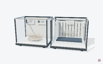
What is the difference between flash point and autoignition temperature?
Flash point asks whether vapour above a liquid can ignite when an ignition source is applied in a specified test. Autoignition concerns ignition without an applied flame or spark under stated test conditions. They are different properties.
Read the complete lesson without the viewer
Separated panels compare an applied ignition source above a liquid with heating without an applied flame or spark; no numerical values are shown.
FS06 · Flash point and autoignition answer different questions
Flash point asks whether vapour above a liquid can ignite when an ignition source is applied in a specified test. Autoignition concerns ignition without an applied flame or spark under stated test conditions. They are different properties.
A momentary flash does not establish sustained burning. Reported properties belong to the actual product and test method; a lower flash point does not imply a lower autoignition temperature. Mists, thin films and absorbent contamination can introduce hazards that a simple bulk-liquid temperature comparison misses.
Eight named structures and concepts
FS06-H01 · Liquid sample
Flash point refers to a liquid tested by a specified method. The illustration is a comparison cabinet, not a reproducible test apparatus.
FS06-H02 · Vapour-air region
The mixture above the liquid is important. For this explanation the flash occurs in the vapour-air region; the liquid does not become a flame throughout its volume.
FS06-H03 · Applied ignition source
The flash-point example includes an applied source. This source distinguishes the left-hand question from the autoignition comparison.
FS06-H04 · Momentary flash
A brief flash need not become sustained burning. A flash-point result and continuing combustion describe different behaviour.
FS06-H05 · Heated environment
The autoignition example has no applied flame or spark. It represents heating under specified test conditions, not an operating-temperature recommendation.
FS06-H06 · Test conditions
A value needs its method and conditions. Results from different methods or different mixtures should not be treated as interchangeable.
FS06-H07 · Product evidence
Use evidence for the actual substance or mixture. The evidence card intentionally contains no invented temperature or copied product value.
FS06-H08 · Mist and contamination
Bulk-liquid flash point does not settle every scenario. A spray, thin film or contaminated absorbent can behave differently from the bulk liquid.
Four illustrative states
Compare the questions
One panel includes an applied ignition source; the other asks about heating without one.
Flash-point explanation
Reveal vapour above the liquid and a brief conceptual flash after the source is applied.
Apply the ignition source Vapour is present above the liquid. The added source starts the brief flash.
A brief vapour flash The left panel shows momentary ignition above the liquid.
The flash fades The flash disappears. A flash-point observation does not establish sustained burning.
Autoignition explanation
Show the heated environment with no added pilot flame or spark.
Heat without a pilot The right panel warms the environment. No pilot flame is applied.
Ignition without an added pilot The right-hand reaction appears after heating. Autoignition asks a different question from flash point.
Interpret the evidence
Check product identity and the test basis. A bulk-liquid property is not an all-scenario safe limit.
Must a liquid with a lower flash point also have a lower autoignition temperature?
Yes These properties answer different questions. An applied ignition source is central to the flash-point comparison.
No Correct. Compare the actual products and stated methods; one property cannot stand in for the other.
HSE, About dangerous substances · HSE HSG140, Safe use and handling of flammable liquids, second edition (2015)
Sources, original geometry and review status
Original editable procedural geometry and illustrations. No third-party fire artwork, atlas, site model or incident footage is copied. Sources establish scientific context; the depiction requires competent scientific and editorial review. Three.js is supplied under its MIT licence.
FS06 HSE, About dangerous substances · HSE HSG140, Safe use and handling of flammable liquids, second edition (2015)
No material-specific values have been added. Missing product, method and conditions remain unverified. This library gives no site approval, prediction or practical certification.
Which technical comparisons should learners be able to explain?
Learners should be able to compare the terms that are often mixed up in vapour cloud and explosion questions.
The terms below often appear in incident reports, DSEAR assessments and practical learning questions. The important skill is not reciting a definition; it is explaining what the term changes in the workplace. Vapour density affects where vapour may collect. Autoignition temperature affects hot-surface risk. Deflagration and detonation describe different combustion speeds and pressure effects. Flash fire and vapour cloud explosion describe different consequences after ignition of a flammable cloud.
A practical answer should always connect the comparison to a decision: where detectors go, whether low points need checking, whether hot surfaces must be controlled, whether people should evacuate, whether a building is vulnerable, or whether specialist explosion assessment is needed.
| Comparison | Plain-English explanation | Why it changes the control strategy |
|---|---|---|
| Vapour density vs air movement | Vapour density describes whether vapour is heavier or lighter than air, but ventilation, wind, temperature and release momentum still affect movement. | Detector placement and emergency exclusion zones should be based on likely cloud behaviour, not only on the substance name. |
| Heavier-than-air vapour vs lighter-than-air gas | Heavier vapours such as LPG or petrol vapour can collect in low areas; lighter gases may rise and accumulate under roofs or poor ventilation pockets. | Low-level drains, pits, bunds and sumps may need monitoring for heavy vapours; roof spaces and high vents may matter for lighter gases. |
| Flash point vs autoignition temperature | Flash point relates to vapour generation from a liquid under test conditions; autoignition temperature is the temperature where ignition can occur without a spark or flame. | A liquid can be controlled at normal temperature but become hazardous when heated, sprayed, misted or exposed to hot surfaces. |
| Flash fire vs vapour cloud explosion | A flash fire burns through a cloud with limited overpressure; a vapour cloud explosion generates damaging pressure, especially where congestion or confinement accelerates flame. | Both can be fatal, but explosion scenarios need stronger attention to layout, building siting, congestion and emergency planning. |
| Deflagration vs detonation | Deflagration has a flame travelling subsonically relative to the unburned mixture; detonation is shock-driven supersonic combustion relative to that mixture. | A deflagration can produce severe overpressure; event classification and site consequences require current specialist assessment. |
| Gas detection vs release prevention | Gas detection warns that a release may be occurring; it does not stop the material escaping. | Detection must be paired with containment integrity, isolation, shutdown, alarm response and ignition control. |
| Purging vs inerting | Purging removes or dilutes flammable vapour from equipment; inerting reduces oxygen so a flammable mixture cannot form. | Both need verified procedures, monitoring and control of re-entry of air or fuel. |
How do flammable vapour clouds form?
Vapour clouds form when released material evaporates, flashes, disperses or mixes with air in a way that creates part of the cloud within the flammable range.
Cloud formation can be rapid or slow. A pressurised release may atomise liquid and flash vapour immediately. A large petrol spill can evaporate across a wide surface. A small leak in a poorly ventilated room can build up over time. A drain or trench can move vapour away from the original release point.
The strongest control is preventing loss of containment. Once a cloud exists, the site is relying on detection, isolation, ignition control, emergency response and people making correct decisions under pressure.
| Release route | How the cloud can form | Control focus |
|---|---|---|
| Overfill | Liquid spills, spreads and evaporates, potentially forming a large ground-level cloud. | Independent overfill protection, alarms, transfer supervision and emergency isolation. |
| Pressurised leak | Jet release can atomise liquid or discharge gas rapidly. | Mechanical integrity, leak detection, isolation and exclusion zones. |
| Open sampling or draining | Vapour is released during routine tasks close to workers and ignition sources. | Closed sampling, permits, bonding/earthing and task supervision. |
| Tank breathing or venting | Vapour exits vents during filling, heating or pressure changes. | Vent design, vapour recovery, hazardous area classification and ignition control. |
| Spill in bund or drain | Liquid or vapour can travel, collect and ignite away from the source. | Drain isolation, bund integrity, spill response and vapour monitoring. |
| Cleaning or maintenance | Residues inside vessels, lines or confined spaces can release vapour. | Gas-freeing, testing, isolation, ventilation and confined-space controls. |
HSE investigates release and vapour-cloud formation in the Buncefield material: HSE Buncefield report.
How do vapour clouds move and disperse?
Cloud movement depends on density, weather, ventilation, obstacles, drains, terrain and how long the release continues.
A cloud is not a neat circle on a drawing. Heavier-than-air vapour can slump, hug the ground and move into low points. Wind can carry vapour downwind. Still conditions or poor ventilation can allow accumulation. Indoors, ventilation patterns, open doors, process ventilation and building geometry can all change cloud movement.
This is why emergency plans should not rely only on the leak source. The plan should consider where the cloud could travel, who might be exposed, which ignition sources need controlling and when evacuation or sheltering decisions are needed.
| Factor | Effect | Practical management point |
|---|---|---|
| Vapour density | Heavier vapours may collect at low level; lighter gases may rise or disperse differently. | Place detectors and ventilation based on gas behaviour, not convenience. |
| Wind and weather | Wind can dilute or transport vapour; still conditions can allow build-up. | Consider weather in emergency response and major accident modelling. |
| Ventilation | Good ventilation can dilute vapour; poor ventilation can allow accumulation. | Verify ventilation performance and maintain extract systems. |
| Release duration | Longer releases create larger clouds and more exposure to ignition sources. | Use detection, isolation and shutdown to reduce duration. |
| Terrain and drainage | Bunds, trenches, sumps and drains can channel vapour or liquid. | Control drains, low points and spill pathways. |
| Obstacles | Plant, pipework and structures can affect turbulence and mixing. | Consider layout and congestion in hazard studies. |
Why do congestion and confinement change explosion severity?
Congestion and confinement can accelerate flame and increase overpressure, turning a flammable cloud into a more destructive explosion scenario.
A vapour cloud can ignite as a flash fire in open space, but severity can increase where flame travels through congested plant, pipe racks, buildings, culverts or partly enclosed areas. Obstacles create turbulence. Confinement restricts expansion. Together they can increase flame speed and pressure.
This is central to process safety layout. Buildings, portable cabins, switch rooms, pump houses, drains and dense pipework should be considered during design and change. A cloud that reaches a vulnerable occupied building or congested enclosure can create consequences far beyond the initial leak.
| Question | Why it matters | Example evidence |
|---|---|---|
| Can a cloud enter buildings or enclosures? | Ignition inside an enclosure can increase explosion severity and expose occupants. | Building siting study, gas ingress controls and ventilation review. |
| Is the plant layout congested? | Obstacles can increase turbulence and flame acceleration. | HAZOP/LOPA records, layout review and VCE assessment. |
| Are drains, culverts or trenches connected? | Vapour can travel unseen to remote ignition sources. | Drain drawings, isolation valves and inspection records. |
| Are temporary structures present? | Cabins, tents or enclosures may add occupancy or congestion. | Temporary siting approval and MOC record. |
| Are ignition sources inside the potential cloud path? | Delayed ignition can produce larger consequences. | Hazardous area drawings, hot-work controls and Ex inspection records. |
| Could emergency responders enter the cloud path? | Response actions may expose people to flash fire or explosion. | Emergency plan, exclusion zones and gas monitoring procedures. |
HSE explosion guidance explains why confinement and obstacles change consequence: HSE EXPLOSION.
How should gas detection and detection limits be understood?
A gas detector samples the conditions at its sensing point and must be selected, located, tested and connected to a defined response for the credited release scenario. A zero or low reading is not proof that the entire area is gas-free.
A detector measures conditions at its location. It can miss a cloud if positioned incorrectly, poorly maintained, inhibited, poisoned, calibrated for the wrong gas or overwhelmed by changing conditions. It can also alarm correctly but fail as a barrier if nobody responds or the alarm action is unclear.
Detector selection should consider gas type, vapour density, release points, ventilation, alarm setpoints, response time, environmental conditions, maintenance and what action follows the alarm. The evidence should include detector maps, calibration records, alarm response procedures, trip testing and proof that people know what to do.
| Topic | What learners should know | What evidence should show |
|---|---|---|
| Detector position | Position depends on release source, gas behaviour and ventilation. | Detector location rationale and layout drawing. |
| Alarm setpoints | Alarms often use percentage of LEL and should trigger defined action. | Setpoint schedule and alarm response procedure. |
| Calibration | Sensors need calibration and may need gas-specific correction. | Calibration certificates and bump-test records. |
| Inhibition or bypass | A disabled detector removes a detection barrier. | Stop or restrict dependent activity; competent assessment and verification of any suitable time-limited alternative before reliance. Keep the bypass register and authorisation evidence. |
| Alarm response | People must know whether to investigate, stop work, isolate, evacuate or shut down. | Training records, drills and control room logs. |
| Maintenance history | Repeated faults can indicate a degraded detection system. | Defect trends, maintenance records and close-out evidence. |
Worked reading: a hypothetical display of 10% LEL at one sensor means that sensor estimates one-tenth of its configured reference lower limit at its location. It does not measure every pocket or justify entry or hot work. The response threshold, calibration gas, cross-sensitivity and gas-test plan come from the competent site-specific design.
HSE gas-detection technical guidance applies to COMAH major-hazard settings; use the actual detector design basis, gas, coverage and response at other workplaces.
Which barriers control vapour cloud fire and explosion risk?
Controls should be layered from release prevention through detection, ignition control, isolation, mitigation and emergency response.
The hierarchy is important. Preventing the release is stronger than detecting a cloud after it forms. Removing ignition sources is stronger than hoping people will avoid them under pressure. Automatic isolation may be stronger than relying on manual action where escalation is rapid.
Barrier management should identify the credible scenario and then ask what prevents it, what detects it, what controls it, what mitigates it and what proves those controls remain healthy today.
| Barrier type | Examples | Assurance evidence |
|---|---|---|
| Prevent release | Mechanical integrity, correct materials, overfill protection, closed transfer and compatible hoses. | Inspection records, proof tests, design data and maintenance history. |
| Limit inventory or release duration | Emergency isolation, shutdown valves, pump trips and transfer limits. | Trip tests, isolation valve tests and operating procedures. |
| Detect release | Gas detectors, leak detection, level alarms and operator rounds. | Detector calibration, alarm logs and response drills. |
| Prevent ignition | Hazardous area classification, Ex equipment, hot-work control, static control and vehicle controls. | DSEAR assessment, Ex register, permits and inspection records. |
| Reduce cloud formation | Ventilation, drainage control, bund design, vapour recovery and spill control. | Ventilation tests, drain plans, bund inspections and emergency procedures. |
| Mitigate consequences | Layout, separation, blast-resistant buildings, evacuation, firefighting and emergency response. | Emergency plans, drills, building siting study and fire protection records. |
Stop or restrict activity that relies on an unavailable credited barrier. A competent assessment must establish and verify any suitable time-limited alternative before reliance; manager or senior approval alone does not establish safety.
How can the hierarchy of controls prevent flammable-vapour clouds and ignition?
Start with elimination and substitution, then engineered isolation, administrative controls and residual PPE. ERICPD adds a discipline/assurance step; it is not a second statutory hierarchy. Each choice below has an owner, test and stop decision.
HSE GB supports dangerous-substance risk principles; HSENI-approved L138 supplies separate NI context only where cited. Examples require competent task assessment and field evidence; engineering design, alarm values and named legal/technical approval remain held.
A transfer continues toward an overfill condition while one independent level safeguard is impaired; consider vapour path, drains, ignition and occupied buildings.
A hose disconnect leaks solvent near a low point; one gas detector reads low while vapour could reach a drain or other unmonitored pocket.
How can the ERICPD hierarchy of controls prevent flammable-vapour clouds and ignition?

| Hazard and harm route | ERICPD → five-level control | Task intervention and feasibility | Owner, test and evidence | Failure and stop decision |
|---|---|---|---|---|
| Petrol-tank overfill and vapour cloud | Eliminate → Elimination | Avoid the transfer until storage capacity and safe receiving route are proven. Source: official guidance. | Operations lead checks inventory and transfer line-up. | Capacity or route uncertain: do not start. |
| Same scenario | Reduce → Substitution | Reduce dangerous inventory or select a safer transfer method where technically feasible. Source: official guidance. | Process authority checks substitute hazards and throughput. | Alternative introduces new uncontrolled release: reject. |
| Same scenario | Isolate → Engineering | Use independent high-level protection, closed transfer, containment and isolation. Source: official guidance. | Engineer proof-tests each credited barrier and records independence. | High-level protection impaired: hold transfer. |
| Same scenario | Control → Administrative | Set transfer limits, line-up verification and alarm response with stop authority. Source: official guidance. | Shift lead witnesses pre-transfer and alarm drill. | Alarm response unclear: stop. |
| Same scenario | PPE → PPE | Use suitable PPE for residual task exposure; it cannot prevent a vapour-cloud explosion. Source: official guidance. | Supervisor checks task PPE and no explosion-control credit. | Plan relies on PPE for blast risk: reject. |
| Same scenario | Discipline → Administrative assurance | Trend overfill signals, bypasses and proof-test failures; verify closed actions. Source: official guidance. | Asset owner signs field effectiveness review. | Repeat signal or open critical defect: stop and reassess. |
| Solvent-vapour release in a semi-enclosed room | Eliminate → Elimination | Remove open solvent handling by redesigning supply or cleaning method. Source: official guidance. | Process engineer trials actual material and task. | Open handling persists as workaround: reject. |
| Same scenario | Reduce → Substitution | Choose lower-volatility or lower-flammability material if process and health risks permit. Source: official guidance. | Technical owner checks full SDS and process performance. | Substitute adds uncontrolled hazard: reject. |
| Same scenario | Isolate → Engineering | Use closed compatible couplings, containment, suitable ventilation and automatic isolation. Source: official guidance. | Engineer leak-tests and challenges worst release path. | Leak, dead ventilation or failed isolation: stop. |
| Same scenario | Control → Administrative | Define gas-test locations, hot-work exclusion, spill response and permit boundaries. Source: official guidance. | Supervisor observes mock release and alarm response. | Single point reading used as all-clear: stop. |
| Same scenario | PPE → PPE | Select chemical splash and respiratory protection for residual exposure by competent assessment. Source: official guidance. | Supervisor verifies compatibility, fit and limits. | PPE used as primary vapour-cloud barrier: reject. |
| Same scenario | Discipline → Administrative assurance | Review detector placement, calibration, alarms and field response after changes. Source: official guidance. | Instrument owner records test and corrective actions. | Unknown coverage or bypass: restrict work. |
How can the ISO 45001 hierarchy of controls prevent flammable-vapour clouds and ignition?

| Hazard and harm route | ERICPD → five-level control | Task intervention and feasibility | Owner, test and evidence | Failure and stop decision |
|---|---|---|---|---|
| Petrol-tank overfill and vapour cloud | Eliminate → Elimination | Avoid the transfer until storage capacity and safe receiving route are proven. Source: official guidance. | Operations lead checks inventory and transfer line-up. | Capacity or route uncertain: do not start. |
| Same scenario | Reduce → Substitution | Reduce dangerous inventory or select a safer transfer method where technically feasible. Source: official guidance. | Process authority checks substitute hazards and throughput. | Alternative introduces new uncontrolled release: reject. |
| Same scenario | Isolate → Engineering | Use independent high-level protection, closed transfer, containment and isolation. Source: official guidance. | Engineer proof-tests each credited barrier and records independence. | High-level protection impaired: hold transfer. |
| Same scenario | Control → Administrative | Set transfer limits, line-up verification and alarm response with stop authority. Source: official guidance. | Shift lead witnesses pre-transfer and alarm drill. | Alarm response unclear: stop. |
| Same scenario | PPE → PPE | Use suitable PPE for residual task exposure; it cannot prevent a vapour-cloud explosion. Source: official guidance. | Supervisor checks task PPE and no explosion-control credit. | Plan relies on PPE for blast risk: reject. |
| Same scenario | Discipline → Administrative assurance | Trend overfill signals, bypasses and proof-test failures; verify closed actions. Source: official guidance. | Asset owner signs field effectiveness review. | Repeat signal or open critical defect: stop and reassess. |
| Solvent-vapour release in a semi-enclosed room | Eliminate → Elimination | Remove open solvent handling by redesigning supply or cleaning method. Source: official guidance. | Process engineer trials actual material and task. | Open handling persists as workaround: reject. |
| Same scenario | Reduce → Substitution | Choose lower-volatility or lower-flammability material if process and health risks permit. Source: official guidance. | Technical owner checks full SDS and process performance. | Substitute adds uncontrolled hazard: reject. |
| Same scenario | Isolate → Engineering | Use closed compatible couplings, containment, suitable ventilation and automatic isolation. Source: official guidance. | Engineer leak-tests and challenges worst release path. | Leak, dead ventilation or failed isolation: stop. |
| Same scenario | Control → Administrative | Define gas-test locations, hot-work exclusion, spill response and permit boundaries. Source: official guidance. | Supervisor observes mock release and alarm response. | Single point reading used as all-clear: stop. |
| Same scenario | PPE → PPE | Select chemical splash and respiratory protection for residual exposure by competent assessment. Source: official guidance. | Supervisor verifies compatibility, fit and limits. | PPE used as primary vapour-cloud barrier: reject. |
| Same scenario | Discipline → Administrative assurance | Review detector placement, calibration, alarms and field response after changes. Source: official guidance. | Instrument owner records test and corrective actions. | Unknown coverage or bypass: restrict work. |
How do purging and inerting reduce flammable atmosphere risk?
Purging and inerting are engineered operations with a specified gas, route, end point and verification. Air purging can pass through a flammable mixture; nitrogen can create an oxygen-deficient atmosphere. A competent task-specific procedure must manage both.
Purging usually means using air, nitrogen, steam or another suitable medium to remove or dilute flammable vapour from equipment before opening, entry, maintenance or start-up. Inerting means reducing the oxygen concentration, often with nitrogen or another inert gas, so the mixture cannot support combustion. Both methods can be powerful controls, but both can be dangerous if misunderstood.
The key teaching point is that purging and inerting are not magic words on a permit. The site must know the material, volume, dead legs, ventilation route, monitoring method, required end point, isolation standard and how the condition will be maintained. Inerting can also introduce asphyxiation risk, so confined space, oxygen monitoring and emergency arrangements may be needed.
| Control | What it does | What must be verified |
|---|---|---|
| Air purge | Dilutes or removes flammable vapour by ventilation with air. | A transition through the flammable range may occur. Competently specify a suitable purge sequence and verified endpoints; control ignition, exposure, isolation and discharge throughout. Air is not a generic safe purge for flammable contents. |
| Nitrogen purge | Displaces flammable vapour or oxygen depending on the method used. | Oxygen levels, discharge route, asphyxiation risk and final gas test results. |
| Steam purge | Can heat and displace vapour in selected systems. | Condensate, pressure, compatibility, burns risk and verified gas-free condition. |
| Inerting | Keeps oxygen below the concentration needed for combustion. | Oxygen concentration, inert gas supply, pressure control, alarms and re-entry of air. |
| Gas testing | Checks atmosphere at defined points after purging or before work. | Instrument calibration, test points, competence and repeat testing frequency. |
| Permit handback | Confirms the equipment remains safe for the next activity. | Isolation status, gas-test record, authorisation and operating limits. |
HSE DSEAR guidance frames inerting as a controlled prevention decision: HSE DSEAR background.
How does DSEAR turn vapour cloud behaviour into workplace controls?
Assess and control the actual dangerous-substance scenario under GB DSEAR 2002 or NI DSEAR 2003. Hazardous-area classification and suitable Ex equipment are parts of the control system, not substitutes for preventing release and controlling ignition.
DSEAR brings the science into management practice. It asks what dangerous substances are present, how an explosive atmosphere could form, how ignition sources are controlled, what areas require classification, what equipment is suitable, what procedures are needed and what emergency arrangements protect people.
ATEX is often discussed alongside DSEAR because it relates to equipment and protective systems used in explosive atmospheres. Good practice does not stop at buying equipment with an Ex mark. The equipment must be suitable for the zone, gas group and temperature class, installed correctly, inspected, maintained and protected from unauthorised change.
| Requirement area | What it means in practice | Evidence |
|---|---|---|
| Dangerous substance identification | Know which gases, vapours, mists, liquids or dusts can create fire or explosion risk. | Substance inventory, SDS review and process condition data. |
| Explosive atmosphere assessment | Identify where flammable mixtures could form during normal and abnormal conditions. | DSEAR assessment and release scenario review. |
| Hazardous area classification | Define zones where special precautions are needed. | Zone drawings, basis of safety and review after change. |
| Ignition source control | Control electrical, static, hot work, mechanical, vehicle and thermal ignition sources. | Ex register, permits, bonding/earthing records and inspections. |
| Equipment suitability | Use equipment suitable for the zone and substance properties. | Equipment certificates, inspection records and maintenance controls. |
| Emergency arrangements | Plan alarm response, isolation, evacuation and firefighting for credible releases. | Emergency plan, drills and gas alarm response records. |
Use HSE GB DSEAR guidance for GB and HSENI-approved L138 for NI; HSE ATEX guidance for GB explosive-atmosphere equipment context.
How do layout, ventilation and drainage reduce vapour cloud risk?
Layout, ventilation and drainage can stop a release becoming a larger cloud, reaching ignition sources or exposing people and occupied buildings.
Good layout separates hazardous inventory from occupied buildings, ignition sources and vulnerable plant. It avoids placing control rooms, cabins or offices in likely cloud paths. It also considers drains, culverts and low points because vapour and liquid can travel in ways that are not obvious from normal walking routes.
Ventilation should be reliable and suited to the release scenario. Natural ventilation may be enough in some open areas, but local exhaust, forced ventilation or gas detection may be needed in enclosed or semi-enclosed spaces. Drainage should prevent flammable liquids spreading to ignition sources or confined spaces.
| Control | What it should achieve | Evidence |
|---|---|---|
| Separation distances | Keep hazardous releases away from people, ignition sources and vulnerable buildings. | Layout review, building siting study and MOC records. |
| Ventilation | Dilute or remove vapour before it reaches dangerous concentration. | Ventilation design, inspection and performance tests. |
| Drain isolation | Prevent flammable liquid or vapour travelling through drains. | Drain plans, isolation valves, inspection logs and spill procedures. |
| Bund design | Contain liquids without creating unmanaged vapour accumulation or escalation pathways. | Bund inspection, capacity checks and emergency response review. |
| Occupied building protection | Avoid siting people where vapour cloud explosion or toxic/fire exposure is credible. | Building occupancy review and emergency plan. |
| Temporary structures | Control cabins, tents and enclosures that create occupancy or congestion near hazards. | Temporary siting approval and permit controls. |
What worked examples make vapour cloud behaviour memorable?
Worked examples help learners move from definitions to practical decisions about releases, alarms, ignition and escalation.
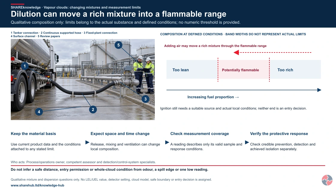
Dilution can move a rich mixture into a flammable range
Full written explanation
An illustrative inactive terminal scene shows a tanker connection, continuous supported hose, fixed-plant connection, surface channel and review papers. Picture key: 1 Tanker connection · 2 Continuous supported hose · 3 Fixed-plant connection · 4 Surface channel · 5 Review papers. The wet ground is not identified as fuel, and no leak, gas, measurement or equipment state is established. A separate qualitative composition band compares too lean, potentially flammable and too rich mixtures under defined substance and test conditions. Increasing fuel proportion points right; a separate opposite arrow shows that adding air may move a rich mixture left through the flammable range. Band widths are not actual limits or a time sequence. Ignition still needs a suitable source and actual local conditions; neither end is an entry or breathing-safety decision. Four unnumbered checks retain material data, space and time variation, valid sampling and achieved protective response. Odour, a spill edge or one low reading does not describe a whole cloud or authorise entry.
Qualitative composition only: limits belong to the actual substance and defined conditions; no numeric threshold is provided.
- Keep the material basis. Use current product data and the conditions attached to any stated limit.
- Expect space and time change. Release, mixing and ventilation can change local composition.
- Check measurement coverage. A reading describes only its valid sample and response conditions.
- Verify the protective response. Check credible prevention, detection and achieved isolation separately.
When the evidence does not fit: Do not infer a safe distance, entry permission or whole-cloud condition from odour, a spill edge or one low reading.
Who acts: Process/operations owner, competent assessor and detection/control-system specialists.
Changed workplace
Solvent storage: Distinguish the liquid footprint from possible vapour pathways.
Fuel handling: Challenge odour and single-sensor assumptions against actual coverage.
Evidence check: Qualitative mixture and dispersion questions only. No LEL/UEL value, detector setting, cloud model, safe boundary or entry decision is assigned.
Read material conditions, detector limitations and achieved protective action
Primary references: HSE flammable-liquid handling publication scope, 2015 · HSE leak/gas detection: purpose, coverage and response
Open the complete HD image (new tab)Download image
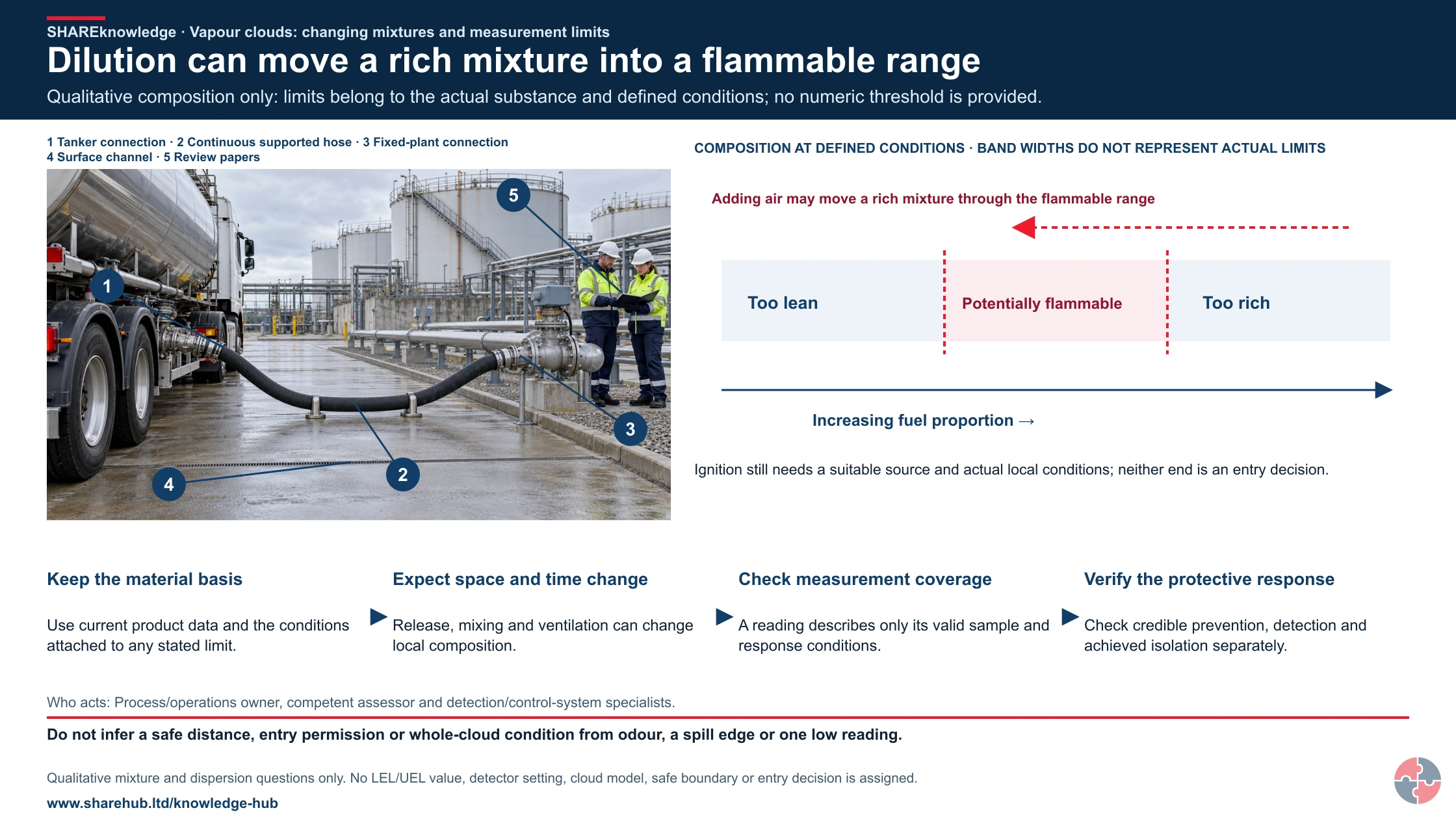
Read material conditions, detector limitations and achieved protective action
Primary references: HSE flammable-liquid handling publication scope, 2015 · HSE leak/gas detection: purpose, coverage and response
These examples are deliberately simple. They show how the same science appears in routine tasks and major hazard operations. The learning point is to ask what has been released, where the cloud could travel, what might ignite it and what barrier should stop escalation.
Use the examples as short toolbox talk prompts or study questions. A good answer should always include at least one prevention barrier, one detection or response barrier and one evidence item.
| Scenario | What is happening | Learning point |
|---|---|---|
| Petrol overfill in a bund | Liquid spreads, evaporates and forms a heavier-than-air vapour cloud. | Overfill prevention and independent high-level protection are vapour cloud controls. |
| LPG leak collecting in a low point | LPG vapour is heavier than air and may collect in pits, drains, basements or low-level poorly ventilated areas. | Low-level gas detection, ventilation, exclusion zones and drain control may be critical. |
| Petrol spill in a bund creates a vapour cloud | Petrol can evaporate rapidly from a large surface area and the bund can hold both liquid and vapour close to ground level. | Bunds control liquid spread but do not remove vapour cloud, ignition or emergency response risk. |
| Solvent spill in a poorly ventilated room | Vapour accumulates until it enters the flammable range. | Ventilation, isolation, spill control and ignition control must be immediate. |
| Solvent vapour moves from too rich to flammable | A concentrated vapour pocket above the UEL becomes ignitable as doors open or ventilation dilutes it into the flammable range. | Ventilation can reduce risk, but the transition through the flammable range must be controlled. |
| Gas detector low alarm near a pump seal | Detector sees vapour at one point, possibly before a larger cloud forms. | Alarm response should stop work, assess the area and control ignition. |
| Gas detector alarms but no one acts | The detector performs correctly, but the organisation has no clear action logic or decision owner. | A warning barrier fails if response actions, shutdowns and escalation rules are not trained and drilled. |
| Hot work near a drained line | Residual vapour remains inside or near equipment after draining. | Gas testing and isolation must consider residues, not just whether liquid has stopped flowing. |
| Hot work after one gas test but vapour returns | A first test is clear, then vapour migrates back from a drain, flange, dead leg or contaminated residue. | Gas testing may need to be repeated or continuous, and the source of vapour must be controlled. |
| Vapour enters a drain | The release travels away from the source and may ignite remotely. | Drain isolation and gas monitoring are part of release control. |
| Temporary cabin placed near process equipment | People are located close to a credible vapour cloud path. | Temporary siting decisions need process safety review. |
| Rich vapour cloud begins to dilute | A mixture above UEL can pass through the flammable range as it mixes with air. | Do not treat 'too rich' as safe during ventilation or dispersal. |
| Aerosol storage with weak ventilation | Leaking or fire-impacted aerosols can release flammable propellant into a store or warehouse area. | Ventilation, separation, ignition control, stock limits and emergency planning should reflect aerosol fire/explosion behaviour. |
Use these regulator routes to check the scenario against GB or NI duties: HSE DSEAR background; HSENI-approved DSEAR code.
Use competent controlled simulations and approved equipment tests for learning. Do not create an actual fuel release, fire, hazardous atmosphere, person-overboard exposure or uncontrolled live-energy/line-tension hazard for a drill.
What do learners commonly confuse about flammability limits?
Learners often confuse substance properties with workplace conditions, or detection readings with full area safety.
This topic becomes much clearer when the common traps are named. LEL is not a magic safe/unsafe boundary for the whole site. Flash point is not the only test of flammable atmosphere risk. Gas detection is not prevention. A cloud that is too rich at one moment can become ignitable as it mixes with air.
The best learning test is whether a person can explain what would make a routine transfer, drain-down, sample, hot-work job or start-up unsafe.
| Confusion | Better explanation | Why it matters |
|---|---|---|
| Below LEL means safe | It means the detector location is below LEL at that moment. | Concentration can vary and detector placement matters. |
| Above UEL means safe | Dilution can bring a rich cloud back into the flammable range. | Ventilation and dispersal can pass through ignitable conditions. |
| Flash point tells the whole story | Process temperature, spraying, pressure and mist formation can change risk. | Some high flash point materials become dangerous in process conditions. |
| Gas detectors prevent explosions | They warn or initiate action; they do not stop release or ignition by themselves. | Response actions and shutdowns must be defined and tested. |
| Gas detector alarms automatically make the area safe | An alarm only creates an opportunity to act; the outcome depends on isolation, evacuation, shutdown and ignition control. | Alarm action logic must be specific, trained and checked through drills. |
| Open air means no explosion risk | Congested or semi-confined areas can still generate damaging overpressure. | Plant layout and structures affect severity. |
| Ignition control is only electrical | Static, hot surfaces, vehicles, mechanical sparks, hot work and friction can ignite vapour. | DSEAR ignition control needs a broad view. |
| DSEAR is only for chemical sites | DSEAR applies wherever dangerous substances can create fire or explosion risk at work. | Warehouses, workshops, laboratories, fuel storage and maintenance work may all be in scope. |
| Purging always makes equipment safe | Purging must be designed, monitored and verified; some purge methods can pass through the flammable range or introduce oxygen/asphyxiation issues. | Permit controls should specify method, test points, acceptance criteria and repeat testing. |
| Autoignition only matters in furnaces | Hot surfaces, exhausts, overheated bearings, heaters and process equipment can exceed autoignition temperature. | Surface temperature control and inspection should be part of ignition-source management. |
| Deflagration means minor explosion | A deflagration can still create severe overpressure where the cloud is large, congested or confined. | Do not understate explosion severity simply because it is not detonation. |
Which major accidents show why vapour cloud behaviour matters?
Use Buncefield and Texas City to test overfill, loss-of-containment, occupied-building and delayed-ignition barriers against local conditions; do not assume those accident sequences or safeguards transfer unchanged to another plant.
Major accidents should be used as learning tools, not as distant stories. The question is not whether a local site looks exactly the same; it is whether the same pattern exists: hazardous inventory, weak level control, poor alarm response, unclear ownership, vulnerable siting, degraded detection, abnormal operation or failure to recognise vapour cloud behaviour.
Buncefield is especially important for UK learners because it involved overfill of petrol storage, vapour cloud formation, delayed ignition, explosion and a major fire. Texas City is important because start-up conditions, hydrocarbon overfilling, alarm and level issues, siting vulnerability and organisational weaknesses combined in a catastrophic refinery explosion.
| Incident | What happened in relation to this topic | Barrier questions for a local site |
|---|---|---|
| Buncefield, UK, 2005 | Petrol overfill led to a large vapour cloud, delayed ignition, explosion, fire, injuries, widespread damage and long-running emergency response. | How are overfills prevented, detected and independently protected? Could vapour reach buildings, drains, ignition sources or occupied areas? |
| Texas City refinery, US, 2005 | Hydrocarbon release during start-up ignited and exploded, killing workers in nearby trailers and exposing weaknesses in control of abnormal operation. | How are start-up inventories, alarms, level control, trailer siting and abnormal conditions managed? |
| Generic solvent room release | A small release in a poorly ventilated room accumulates until a switch, heater or static discharge ignites it. | Are ventilation, detectors, Ex equipment, storage limits and spill response checked in ordinary workplaces? |
| Generic tanker transfer overfill | A transfer continues after expected stop point and vapour reaches a remote ignition source. | Are transfer supervision, independent alarms, emergency stop and site drainage controls verified? |
Read the HSE Buncefield materials and the US CSB Texas City investigation as incident learning, then verify the local design basis.
What good evidence shows vapour cloud risk is controlled?
Good evidence connects substance data, credible releases, hazardous areas, detectors, ignition controls, procedures and emergency response.
This is where many pages and assessments become weak. It is not enough to say that flammable materials are controlled. The organisation should be able to show which substances can form a cloud, where that cloud could travel, what might ignite it, what stops the release, what detects it, what isolates it and how people respond.
Evidence should be sampled during audits. Review real permits, detector calibrations, alarm histories, maintenance backlogs, DSEAR drawings, near misses, change records and emergency drill learning.
| Evidence | What it proves | Weak signal |
|---|---|---|
| Substance inventory | The site knows which dangerous substances are present and where. | Unlisted temporary materials, samples or waste streams. |
| SDS and property data | Flash point, LEL/UEL, vapour density, autoignition and compatibility are understood. | Data missing from procedures or training. |
| DSEAR assessment | Explosive atmosphere risks have been assessed and controls defined. | Assessment not updated after process or layout change. |
| Hazardous area drawings | Zones are defined and equipment suitability can be checked. | Out-of-date drawings or equipment installed without review. |
| Gas detector register | Detector type, position, setpoints and calibration are controlled. | Repeated detector faults or bypasses. |
| Permit and hot-work records | Ignition sources are controlled during non-routine work. | Generic permits with no vapour pathway or gas-test detail. |
| Barrier proof tests | Trips, alarms, isolation and shutdowns work when demanded. | Overdue proof tests or deferred maintenance. |
| Emergency drills | People know how to respond to gas alarms and vapour releases. | Confusion over muster, isolation or evacuation route. |
| Incident and near-miss trends | Weak signals are reviewed for common barrier failure. | Leak reports closed locally with no trend review. |
Which GB and Northern Ireland duties apply?
Great Britain DSEAR 2002 and Northern Ireland DSEAR 2003 are separate workplace routes. General work-health and COMAH regimes also differ; COMAH applies only to qualifying establishments.
DSEAR duties include prevention and mitigation, information and training, and emergency arrangements. A site-specific hazardous-area or fire strategy needs competent design and verification.
Identify the site jurisdiction, activity, material and threshold before applying a statutory requirement. HSE guidance explains GB controls; HSENI-approved L138 supports NI interpretation.
| Jurisdiction | Duty or regulation | When it is relevant | Practical implication |
|---|---|---|---|
| GB | DSEAR 2002 | GB dangerous-substance and explosive-atmosphere duties. | Scenario assessment, prevention, mitigation, hazardous-area basis and emergency evidence. |
| NI | DSEAR (NI) 2003 | Separate NI dangerous-substance and explosive-atmosphere duties. | NI assessment, prevention, mitigation and emergency evidence. |
| GB | Health and Safety at Work etc. Act 1974 | GB general work-health duties. | Risk ownership, worker information and corrective action. |
| NI | Health and Safety at Work (NI) Order 1978 | Separate NI general work-health duties. | NI risk ownership and corrective action. |
| GB | Management Regulations 1999 | GB risk assessment and arrangements. | Updated assessment, competence and emergency roles. |
| NI | NI Management Regulations 2000 | NI risk assessment and arrangements. | Updated NI assessment and emergency roles. |
| GB | COMAH 2015 | GB major-accident route at qualifying establishments only. | Threshold check and safety report if required. |
| NI | COMAH (NI) 2015 | Separate NI major-accident route at qualifying establishments. | Threshold check and NI major-accident evidence. |
For practical interpretation use HSE GB DSEAR and HSENI L138 for the NI instrument.
What should a vapour cloud risk register include?
A useful risk register should connect release scenarios to the controls and evidence that prevent, detect, isolate and mitigate vapour cloud events.
The register should be scenario-led. A row labelled 'flammable liquids' is too broad to manage. A stronger row identifies a specific transfer, vessel, pump seal, drain, sampling point, vent, storage area or maintenance task and describes what can go wrong.
For high-risk sites, the register should identify which barriers are safety-critical and what proof is required. That includes level instruments, trips, alarms, gas detectors, emergency isolation, ventilation, hazardous area equipment, permits and emergency response.
| Scenario | Main barriers | Evidence |
|---|---|---|
| Tank overfill during petrol transfer | High-level alarm, independent overfill protection, transfer supervision, emergency stop and bund control. | Proof test records, transfer procedure, alarm response drill and Buncefield-style learning review. |
| Pump seal leak in a solvent process area | Mechanical integrity, gas detection, hazardous area equipment, isolation valve and emergency response. | Seal inspection, detector calibration, Ex register and isolation test. |
| Hot work near a drained flammable line | Isolation, cleaning, gas testing, permit-to-work, fire watch and ignition control. | Permit records, gas-test log, isolation certificate and supervisor check. |
| Vent release from a storage tank | Vent design, vapour recovery, hazardous area classification and ignition control. | Design basis, inspection record, zone drawing and MOC review. |
| Vapour ingress into occupied building | Separation, ventilation control, gas detection, building siting and evacuation plan. | Building risk review, detector evidence and emergency drill. |
How could Crownway Fuels Ltd manage vapour cloud behaviour?

Crownway Fuels Ltd would manage vapour cloud behaviour through DSEAR assessment, major accident scenario control and disciplined assurance of critical barriers.
Crownway Fuels Ltd
Crownway Fuels Ltd is a fuel storage and distribution business used by SHARE to show how process safety topics apply in practice.
Crownway begins with substance and scenario mapping. The site lists petrol, diesel, additives, LPG cylinders, cleaning solvents and waste streams, then identifies where releases could occur: tank overfill, loading arm failure, tanker coupling leak, pump seal failure, drain contamination, sample point release and maintenance opening of lines.
The DSEAR assessment links each scenario to hazardous area drawings, ignition-source controls, gas detection, emergency isolation, transfer procedures, overfill prevention, bunding, drainage and emergency response. The major accident register identifies which barriers prevent a Buncefield-type vapour cloud event, which detect it early and which reduce consequences if a release occurs.
Training is role-specific. Operators learn LEL alarm meaning, vapour density, drain pathways, transfer stop rules and emergency isolation. Supervisors learn permit controls, detector bypass authorisation and restart decisions. Engineering teams maintain detectors, valves, level instruments, pumps and Ex equipment. Leaders review trends in leaks, alarms, proof tests, maintenance deferrals, permit findings and emergency drill learning.
Assurance is layered. Frontline workers complete binary checks on transfer line-up, bonding, drain covers, alarm status and ignition controls. Second-line HSSE and engineering audits sample DSEAR evidence, detector calibrations, proof tests and permits. Third-line specialists periodically review modelling assumptions, hazardous area classification, occupied building risk and major accident barriers.
| Management element | How Crownway would manage it | Evidence |
|---|---|---|
| Substance knowledge | Maintain a flammable substance register with LEL, UEL, flash point, vapour density and process conditions. | Substance register, SDS review and DSEAR data sheet. |
| Scenario register | Define tank, loading, pump, drain, sampling and maintenance release scenarios. | DSEAR assessment and major accident hazard register. |
| Barrier assurance | Proof test overfill protection, emergency isolation, gas detection and alarms. | Proof test schedule, calibration records and alarm response checks. |
| Ignition control | Control hot work, static, vehicles, electrical equipment, contractors and temporary plant. | Permit records, Ex register and inspection reports. |
| Training and competence | Train operators, supervisors, engineers and emergency teams to role-specific standards. | Training matrix, competence checks and drill records. |
| Learning and improvement | Trend leaks, gas alarms, false alarms, bypasses, permit findings and abnormal transfers. | Management review, action tracker and incident learning records. |
Stop or restrict activity that relies on an unavailable credited barrier. A competent assessment must establish and verify any suitable time-limited alternative before reliance; manager or senior approval alone does not establish safety.
Use competent controlled simulations and approved equipment tests for learning. Do not create an actual fuel release, fire, hazardous atmosphere, person-overboard exposure or uncontrolled live-energy/line-tension hazard for a drill.
What does a fuel example show about vapour-cloud behaviour?
Look for vapour spaces, vent outlets and low spaces as distinct assessment inputs. The scene does not calculate concentration, flammable limits or dispersion.
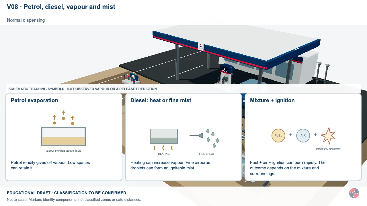
Petrol, diesel, vapour and mist
Compare petrol evaporation, diesel conditions and fine droplets. Petrol carried into a separator can remain a vapour source after the visible forecourt spill has passed.
Activity focus: Identify the actual product and release mechanism. For drainage, ask whether petrol could reach or remain in the separator; for refuelling, confirm the stated Stage II recovery arrangement.
Contextual illustration. The image alone does not establish equipment state, effective controls, individual health or authorisation; use the task-specific checks and competent evidence.
Educational illustration, not to scale. Coloured zones are teaching examples, not a site-specific hazardous-area classification.
Who needs competence to manage flammability limits and vapour-cloud behaviour?
Test the decisions each role makes during an abnormal release or impaired barrier; attendance alone does not demonstrate competence.
| Role | Learning to test | Competence demonstration | Assessor and record | Reassessment trigger |
|---|---|---|---|---|
| Operators | Recognise substance, release and abnormal condition. | Explain alarm, isolation and withdrawal in a task simulation. | Supervisor records observed response. | New substance, task, alarm or shift pattern. |
| Supervisors | Verify permit, stock, contractor and impairment boundaries. | Challenge a changed transfer and stop-work decision. | DSEAR owner reviews field evidence. | Layout, process or staffing change. |
| Maintenance and instrument staff | Test credited containment, ventilation and detection. | Show proof test and defect escalation on actual equipment. | Engineering authority signs record. | Failed test, bypass or design change. |
| DSEAR assessor | Assess credible release, ignition and mitigation under GB or NI law. | Defend scenario, area classification and uncertainty. | Independent competent reviewer signs assessment. | Material, inventory or legal change. |
| Site leader | Resource control and stop a degraded critical barrier. | Review scenario and hand-back evidence. | Governance meeting records decision. | Major event or repeated weak signal. |
Stop or restrict activity that relies on an unavailable credited barrier. A competent assessment must establish and verify any suitable time-limited alternative before reliance; manager or senior approval alone does not establish safety.
Use competent controlled simulations and approved equipment tests for learning. Do not create an actual fuel release, fire, hazardous atmosphere, person-overboard exposure or uncontrolled live-energy/line-tension hazard for a drill.
How does this support process-safety study?
This topic supports process safety study by linking technical flammability concepts to major accident scenarios, barriers and management evidence.
Learners should be able to explain LEL, UEL, flash point, autoignition, vapour density, congestion, confinement, dispersion and detection limits in plain English. They should then apply those terms to a scenario such as tank filling, pump seal leak, hot work, start-up, solvent storage or gas alarm response.
A strong exam answer will not stop at definitions. It will describe how the vapour cloud could form, what might ignite it, what barriers should prevent or control it, what evidence proves the barriers are working and what major accident learning is relevant.
| Prompt | What a strong answer should include | Related page |
|---|---|---|
| Explain the difference between LEL and UEL. | Too lean, flammable range, too rich, dilution risk and detector limitations. | ATEX and Explosive Atmospheres |
| Describe how a vapour cloud explosion could develop after tank overfill. | Overfill, spreading liquid, evaporation, cloud movement, delayed ignition, congestion and overpressure. | BLEVE Hazards |
| Explain why gas detection is not enough on its own. | Detector placement, calibration, alarm response, isolation, ignition control and emergency action. | Fire and Gas Detection, Alarms and Shutdown |
| Explain how DSEAR controls explosive atmospheres. | Dangerous substance assessment, zoning, ignition control, equipment suitability and emergency arrangements. | Dangerous Substances and Hazardous Properties |
| Describe why Buncefield is relevant to vapour cloud behaviour. | Overfill, petrol vapour cloud, delayed ignition, explosion, fire, barrier failure and learning. | Bowtie Analysis and Barrier Management |
How can BS EN ISO 45001 support flammability limits and vapour cloud behaviour management?
A voluntary occupational health and safety system can assign owners for substance information, credible release scenarios, barrier checks, competence, change and learning. Process engineering and the applicable DSEAR or COMAH route remain separate obligations.
HSE public guidance supports practical management themes in Great Britain. ISO clause mapping, conformity and certification claims remain held for current licensed-text and specialist review; this page does not establish compliance or certification.
What are the warning signs that vapour cloud risk is not controlled?
Weak control usually appears as small leaks, detector problems, permit shortcuts, poor ignition control, outdated DSEAR records and unclear alarm response.
These warning signs should be treated as process safety weak signals. A small leak, repeated detector fault or generic hot-work permit may not cause harm today, but it may show that the vapour cloud barriers are degrading.
The important question is whether the organisation learns from weak signals or treats them as isolated housekeeping issues.
| Warning sign | How it can lead to harm | Action |
|---|---|---|
| Repeated small leaks | A larger release may be normalised until it forms a flammable cloud. | Trend leaks and review mechanical integrity. |
| Gas detectors frequently bypassed | Detection barrier may be unavailable during a release. | Stop or restrict activity that relies on an unavailable credited barrier. A competent assessment must establish and verify any suitable time-limited alternative before reliance; manager or senior approval alone does not establish safety. |
| Generic hot-work permits | Ignition sources may be introduced without understanding vapour pathways. | Improve permit questions, gas testing and supervision. |
| Outdated hazardous area drawings | Unsuitable equipment may be installed in a flammable atmosphere. | Review zoning after changes. |
| Poor drain control | Vapour or liquid may travel to remote ignition sources. | Inspect drains, isolate where needed and update emergency plans. |
| Alarm response unclear | People may delay isolation or evacuation while the cloud grows. | Drill alarm response and define decision authority. |
| Maintenance deferrals on safety-critical equipment | Trips, alarms or isolation may not work on demand. | Stop or restrict activity that relies on an unavailable credited barrier. A competent assessment must establish and verify any suitable time-limited alternative before reliance; manager or senior approval alone does not establish safety. |
Stop or restrict activity that relies on an unavailable credited barrier. A competent assessment must establish and verify any suitable time-limited alternative before reliance; manager or senior approval alone does not establish safety.
What do the acronyms and key terms mean?
Acronyms should be explained so operators, managers, engineers and learners can discuss the same risk clearly.
| Acronym | Meaning | Plain-English use |
|---|---|---|
| ATEX | Atmospheres Explosibles | Common shorthand for equipment and protective systems used in explosive atmospheres. |
| COMAH | Control of Major Accident Hazards Regulations | Major hazard regime for qualifying establishments. |
| DSEAR | Dangerous Substances and Explosive Atmospheres Regulations | Main UK workplace fire and explosion regulation for dangerous substances. |
| Ex | Explosion-protected equipment | Equipment designed for use in hazardous areas where explosive atmospheres may occur. |
| LEL | Lower Explosive Limit | Lowest fuel concentration in air that can ignite. |
| LFL | Lower Flammable Limit | Another term commonly used for LEL. |
| UEL | Upper Explosive Limit | Highest fuel concentration in air that can propagate flame. |
| UFL | Upper Flammable Limit | Another term commonly used for UEL. |
| VCE | Vapour Cloud Explosion | Explosion after delayed ignition of a flammable vapour cloud. |
| GB | Great Britain | GB DSEAR and COMAH route. |
| NI | Northern Ireland | Separate NI DSEAR and COMAH route. |
| ERICPD | Eliminate, Reduce, Isolate, Control, PPE, Discipline | Teaching aid for control selection and assurance. |