
SHARE Knowledge Hub
LEV Local Exhaust Ventilation
Local exhaust ventilation (LEV) captures or contains airborne contaminant at source before it crosses a worker’s breathing zone. It must be designed for the task, commissioned against a clear performance standard, checked by users, maintained and thoroughly examined and tested. A fan running or an in-date test label does not prove capture during the real task.
Understanding LEV Local Exhaust Ventilation
Local exhaust ventilation (LEV) captures or contains airborne contaminant at source before it crosses a worker’s breathing zone. It must be designed for the task, commissioned against a clear performance standard, checked by users, maintained and thoroughly examined and tested. A fan running or an in-date test label does not prove capture during the real task.
Why this matters at work
Health outcomes depend on substance, concentration, particle size, exposure duration and individual susceptibility. Effects may include irritation, occupational asthma, chronic obstructive pulmonary disease, silicosis, allergic alveolitis, metal fume effects, systemic toxicity and cancer. Some substances can also damage skin or eyes, be ingested from contaminated hands and surfaces, or create fire and explosion hazards independent of their toxic effect.
Airborne hazards include solid dusts, fumes formed by condensation of vaporised material, liquid mists, gases, vapours and biological aerosols. The visible cloud may represent only part of the hazard. Fine respirable particles can remain airborne and enter deep lung regions; invisible vapours or gases may travel with room air; larger inhalable particles can affect the nose, mouth and upper respiratory tract or settle and become a secondary source.
How organisations manage this in practice
Begin by preventing exposure. Eliminate the hazardous substance or emission-generating step where reasonably practicable; substitute a safer material, form or process; reduce quantity, temperature, pressure, energy or duration; enclose or automate the source; and design handling so contamination is not released. LEV is often essential, but it should not preserve an avoidable dusty or fuming process unchanged.
Exposure monitoring measures contaminants in air to answer questions that system measurements cannot. Use it where the assessment cannot otherwise show adequate control, where a WEL or internal benchmark must be tested, where risk is high, or where process and control variability create uncertainty. Monitoring should follow a suitable strategy and method led by competent occupational-hygiene judgement.
Coordinate contractors and shared workplaces. Define who supplies process information, shuts down work, isolates energy, cleans the system, provides access, accepts the report and verifies repairs. Review contractor LEV brought to site and host systems used by contractors. A hire unit, service label or method statement does not prove control for the host task.
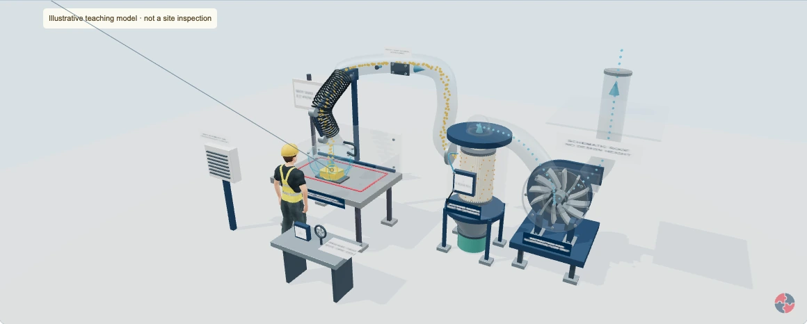

LEV: follow the harmful substance out of the breathing zone
Move the capturing hood, watch the fan draw air through connected ductwork and follow harmful dust or particulate fume away from the breathing zone. Move the work beyond the marked bench area to see why a running fan can still leave people exposed.
Checksheets and risk assessments
Equipment checksheets
Risk assessment forms
Risk assessment examples
Forms and tools
Full written walkthrough — all 13 steps
1. Identify the source, task and people
What is happening: The source marker represents airborne dust or particulate fume released by a task. The same task may expose the operator, neighbours, cleaners and maintenance staff.
How harm can occur: Contaminant reaching a breathing zone can be inhaled; the type of harm depends on the substance, exposure and person.
Best practice to apply: Assess the actual substance and work. Consider elimination, substitution and source reduction before selecting suitable extraction and other controls.
2. Position the hood close to the source
What is happening: The hood is raised. Its flexible duct and jointed support remain connected, but the source is further from the hood mouth. Use Lower hood or drag the hood-position control.
How harm can occur: The capture effect weakens rapidly with distance. A contaminant cloud can pass through the breathing zone while the fan keeps turning.
Best practice to apply: Position the hood as specified for the actual task. Use the commissioning information and a representative competent test to establish the allowed source position, height and full working movement.
Why this works: Air speed at the source matters. Neither a strong draught at the hood mouth nor the sound of a fan proves effective capture where the work happens.
LEV Local Exhaust Ventilation · What are capture zones, working zones and breathing zones?3. Lower the hood and keep the source in range
What is happening: The open flanged hood is lowered towards the source. Air is drawn towards the mouth and into the flexible duct. The red tape marks only an illustrative bench footprint; source height and the whole tool movement matter too. The translucent blue volume shows an illustrative three-dimensional capture envelope: source height and sideways distance both matter. Select Move the hood or Move the workpiece to drag them independently around the bench.
How harm can occur: A source beyond the effective capture zone can release contaminant into the worker’s or a bystander’s breathing zone, even with the fan running.
Best practice to apply: Have a competent person test the actual process, hood, source position/height, airflow and expected draughts. Mark the verified working footprint on the bench and record the maximum position/height and hood setting. Keep the full working zone inside it; change the hood or method if this is impractical. A real capture envelope must be established by representative competent testing; the blue shape is not a measured safe boundary.
Why this works: A visible position mark helps repeat the tested arrangement. It is a positioning aid, not a certificate, a universal distance or proof that changed conditions remain controlled.
LEV Local Exhaust Ventilation · What are capture zones, working zones and breathing zones?4. Watch the impeller draw air away
What is happening: The cutaway shows a slowly rotating impeller connected to a fixed motor. Press Animate fan and airflow to turn the rotor and follow the arrows from source to hood, duct, filter, fan and discharge. The real guard and casing stay closed.
How harm can occur: Loss of flow can allow the source cloud to escape; moving fan parts create separate servicing hazards.
Best practice to apply: A running fan or a single pressure indication does not prove capture. Check suitable indicators and interpret measurements against the real design/commissioning basis.
5. Stop: work has moved outside the marked area
What is happening: The workpiece moves beyond the red bench mark. The fan continues running, but most of the illustrative cloud misses the hood and escapes towards people. The same hood has less capture effect at the more distant source. Try moving the hood towards the workpiece. The teaching cloud changes when the full source moves into or out of the three-dimensional envelope; changing the real arrangement still needs verification.
How harm can occur: Dust or fume can be inhaled by the operator or nearby workers. Moving the work outside the tested capture zone can defeat otherwise functioning extraction.
Best practice to apply: Stop the contaminant-generating task. Move the work back into the verified zone, reposition the hood or choose a more suitable control. Check the indicator and have changed arrangements verified before restarting.
Why this works: A bench mark helps repeat a tested arrangement; it is not a physical wall. The hood must control the full cloud, including the edges of the work and its movement.
LEV Local Exhaust Ventilation · What are capture zones, working zones and breathing zones?6. Restore the working position and recheck
What is happening: The workpiece returns inside the illustrative footprint and the hood is lowered. The dust/fume path is drawn into the hood again in this teaching example.
How harm can occur: A different material, source height, tool movement or cross-draught may still defeat capture even after moving the work back.
Best practice to apply: Repeat the actual verified arrangement and pre-use checks. If reliable control cannot be restored, keep the task stopped and report the defect. Do not use the animation as an exposure measurement. A moved hood requires review of the new three-dimensional working zone; do not rely on the old tape mark.
LEV Local Exhaust Ventilation · What are capture zones, working zones and breathing zones?7. Carry the contaminant through the duct
What is happening: The cutaway follows the contaminant-bearing stream through connected ductwork. Flanges, access and a test point are visible.
How harm can occur: Leaks, deposits, damage or obstructions can impair control and expose people during operation or maintenance.
Best practice to apply: Use suitable design and actual inspection/measurement. The moving dots show a route, not a calculated velocity, concentration or leak test.
8. Separate suitable particles in the cleaner
What is happening: Inspect the pleated cartridge. Amber teaching particles collect on the outer media; the blue carrier-air path continues from the inner side.
How harm can occur: Damaged, unsuitable or heavily loaded media can impair control. A particulate filter does not establish removal of gases or vapours.
Best practice to apply: Select and verify cleaning appropriate to the actual contaminant and process. No filtration efficiency or safe discharge concentration is calculated.
9. Contain and handle collected material
What is happening: Follow the separated material towards the closed hopper/bin. Dust does not stop being hazardous because it has left the breathing zone.
How harm can occur: Opening, emptying or changing components may release dust; combustible material can introduce fire/explosion hazards.
Best practice to apply: Use suitable containment, isolation, waste handling and substance-specific precautions. The model does not approve collection of combustible or reactive dust.
10. Stop: the fan is off but the source can still release
What is happening: The impeller stops and the air-path arrows disappear. The source may continue releasing harmful material until the actual process is stopped or otherwise made safe.
How harm can occur: Without extraction, the contaminant can spread into the breathing zone. A hidden motor failure or disconnected supply may leave a task uncontrolled.
Best practice to apply: Stop the affected task, report the fault and follow the site procedure. Any automatic interlock needs separate design and testing; this model does not simulate one.
LEV Local Exhaust Ventilation · What are capture zones, working zones and breathing zones?11. Compare a loaded filter with a running fan
What is happening: The fan still rotates. Collected material is shown on the cartridge; slower symbolic tracers and escaped particles illustrate possible reduced capture as system resistance changes.
How harm can occur: A running motor does not prove the specified airflow. A blocked or damaged filter, leaking duct or changed system can leave people exposed.
Best practice to apply: Compare suitable airflow and pressure indicators with the actual commissioning data. Investigate defects; isolate before intrusive maintenance and control exposure to collected material.
LEV Local Exhaust Ventilation · What are capture zones, working zones and breathing zones?12. Consider discharge and replacement air
What is happening: Blue particles identify the continuing air route beyond the fan. Blue does not mean the discharge has been proven harmless.
How harm can occur: An unsuitable discharge or air-supply arrangement can expose other people or disturb capture at the source.
Best practice to apply: Assess actual contaminant removal, discharge, nearby intakes and replacement air. No dispersion, discharge height or safe separation is established.
13. Verify performance and review changes
What is happening: The measurement station connects design, commissioning, routine checks, maintenance, examination/testing and review. Its instruments do not display measured results.
How harm can occur: A system that looks intact can still leave people exposed, especially when tasks, materials or operating conditions change.
Best practice to apply: Use competent performance verification and exposure assessment where needed. Record defects and stop affected work when control is unreliable.
Illustrative awareness learning. The model does not design equipment, authorise work, verify safe conditions or complete a real inspection.
The wider workplace has its own account and subscription access. Exploring this lesson does not grant access, record course completion or authorise work.
UK guidance for further reading
HSE: local exhaust ventilationHSE HSG258: controlling airborne contaminantsHSE: COSHHHow can I practise this topic in 3D?
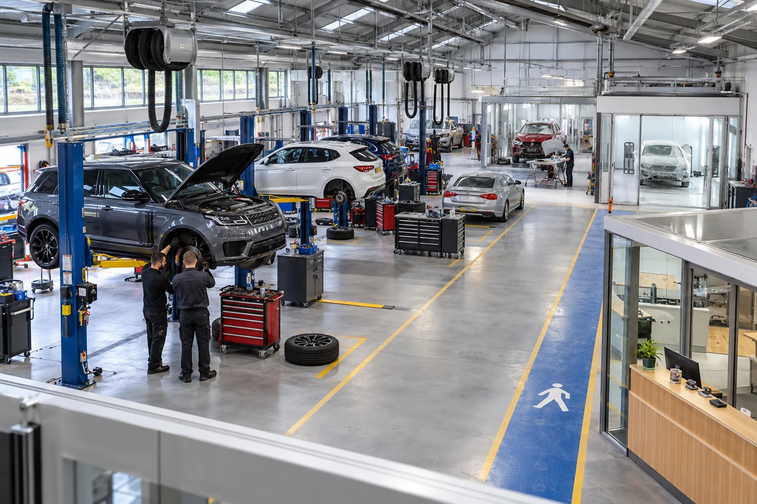
Sanding dust escapes from the repair bay
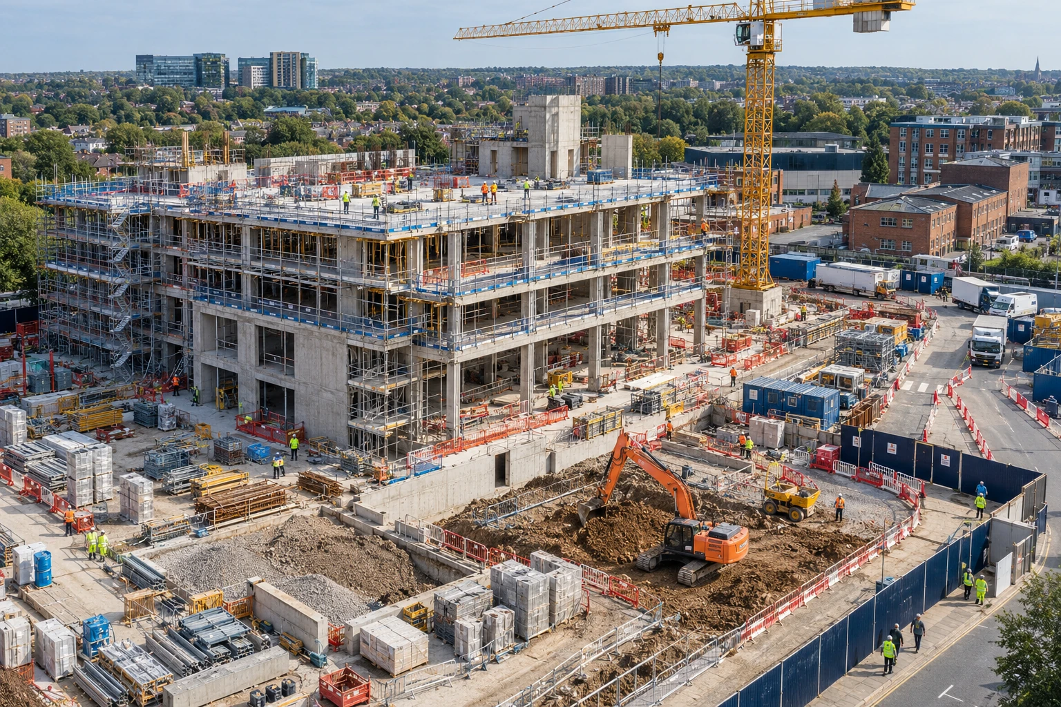
Hot work is proposed outside the controlled bay
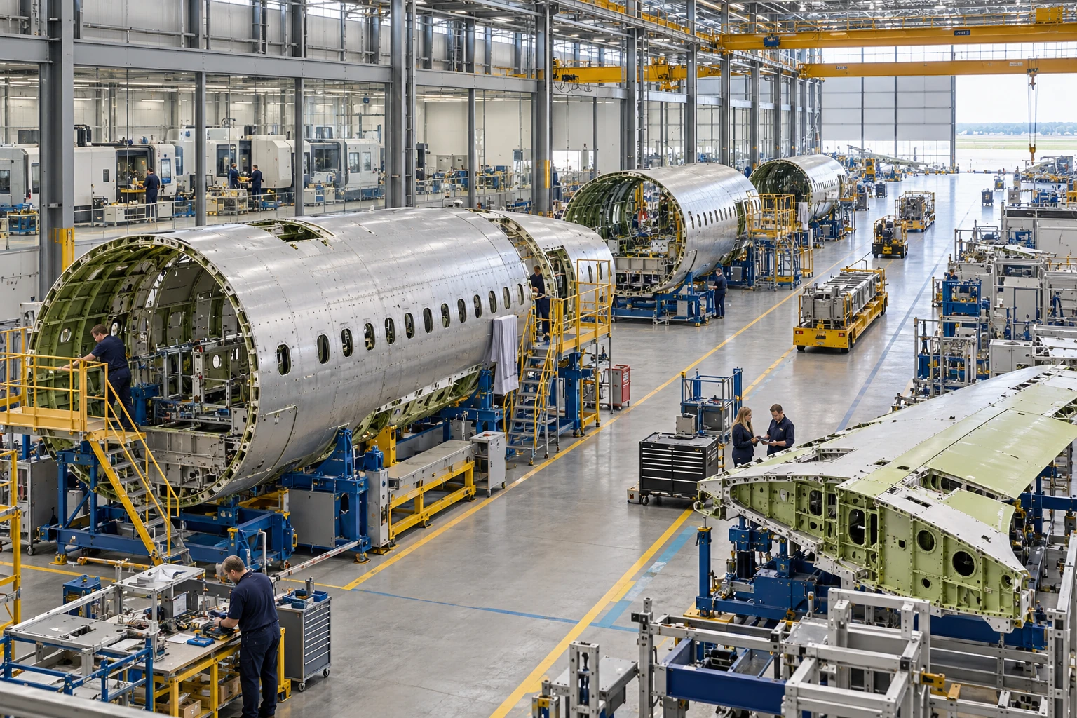
LEV capture and dust collection
All related inspection points 7 across 3 locations
Garage workshop 4 inspection points
Construction site 1 inspection point
Aerosystems Engineering 2 inspection points
Practice in the SHAREhub environment. Browser practice is separate from workplace competence and formal learning records.
What are the key facts about LEV?
The most important point is that LEV only protects people when it captures the contaminant before it reaches the breathing zone.
Best-practice guide: LEV Local Exhaust Ventilation
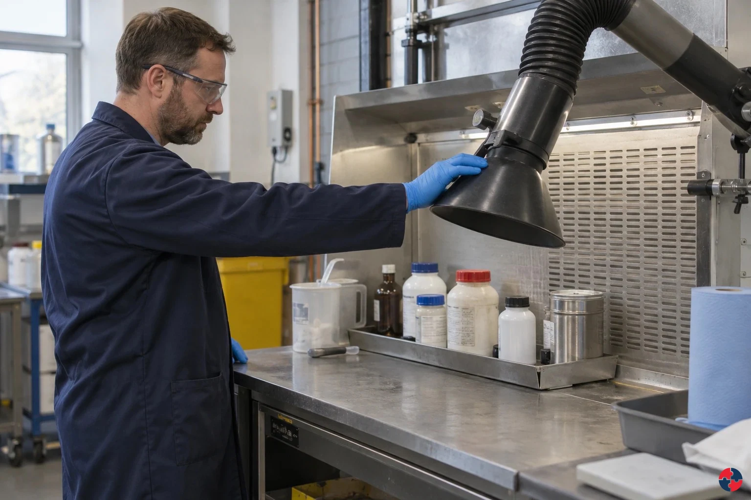
What are the key facts about LEV?
The most important point is that LEV only protects people when it captures the contaminant before it reaches the breathing zone. Local exhaust ventilation (LEV) captures or contains airborne contaminant at source before it crosses a worker’s breathing zone.
Turn lev local exhaust ventilation knowledge into a decision
Local exhaust ventilation (LEV) captures or contains airborne contaminant at source before it crosses a worker’s breathing zone. It must be designed for the task, commissioned against a clear performance standard, checked by users, maintained and thoroughly examined and tested. COSHH register, LEV asset register and health-risk map.
the site team worked example
Assessing: the site team identifies dust, fume, mist and vapour tasks and links each LEV asset to a COSHH assessment and health risk. Evidence / response: COSHH register, LEV asset register and health-risk map. Specifying: LEV purchases require task description, contaminant type, worker position, capture requirement and commissioning evidence. Evidence / response: LEV procurement specification and acceptance test.
LEV warning signs and actions
Visible dust, fume or mist escapes: Capture or containment is failing. Airflow gauge out of range: System may be blocked, leaking or unbalanced. No commissioning report: No benchmark for performance.
Choose controls for lev local exhaust ventilation
Eliminate: Buy prefinished parts or avoid dusty cutting/sanding where feasible. Reduce: Use a lower-dust product and less dust-generating tool/method. Isolate: Fit task-specified on-tool extraction/LEV, enclose or separate the emission, and provide make-up air. Control: Position hood/tool correctly, check airflow indicator, clean safely and maintain filters. PPE: Provide suitable RPE and other protection for remaining exposure. Read the full control table for qualifications, ownership and verification. Use the actual task and applicable jurisdiction; existing technical approval remains unchanged.
Use the full lev local exhaust ventilation lesson
Use the full topic for the decision points, practical examples, detailed control tables and source scope. HSE guidance applies to Great Britain; use HSENI for the Northern Ireland route and the source’s stated jurisdiction. A simplified guide does not change the page’s technical-review or approval status.

Read all six steps as text
1. What are the key facts about LEV?
The most important point is that LEV only protects people when it captures the contaminant before it reaches the breathing zone.
- Avoid / redesign: Buy prefinished parts or avoid dusty cutting/sanding where feasible.
- Control the task: Fit task-specified on-tool extraction/LEV, enclose or separate the emission, and provide make-up air.
- Verify before release: Process owner checks feasibility; undocumented process change holds work.
The most important point is that LEV only protects people when it captures the contaminant before it reaches the breathing zone. Local exhaust ventilation (LEV) captures or contains airborne contaminant at source before it crosses a worker’s breathing zone.
Apply it: Which part of this plan would you check at the workface before authorising the task?
2. Turn lev local exhaust ventilation knowledge into a decision
Use the evidence to improve the actual work arrangement.
- Change at source: Buy prefinished parts or avoid dusty cutting/sanding where feasible.
- Make it observable: Process owner checks feasibility; undocumented process change holds work.
- Keep useful evidence: COSHH register, LEV asset register and health-risk map.
Local exhaust ventilation (LEV) captures or contains airborne contaminant at source before it crosses a worker’s breathing zone. It must be designed for the task, commissioned against a clear performance standard, checked by users, maintained and thoroughly examined and tested. COSHH register, LEV asset register and health-risk map.
Apply it: What evidence would show that the change improves this task, rather than only completing a record?
3. the site team worked example
Example: a practical application of the existing topic lesson.
- Assessing: the site team identifies dust, fume, mist and vapour tasks and links each LEV asset to a COSHH assessment and health risk.
- Specifying: LEV purchases require task description, contaminant type, worker position, capture requirement and commissioning evidence.
- Implementing: Operators use hoods, on-tool extraction, booths and gauges correctly, with stop-work triggers for failed capture.
Assessing: the site team identifies dust, fume, mist and vapour tasks and links each LEV asset to a COSHH assessment and health risk. Evidence / response: COSHH register, LEV asset register and health-risk map. Specifying: LEV purchases require task description, contaminant type, worker position, capture requirement and commissioning evidence. Evidence / response: LEV procurement specification and acceptance test.
Apply it: At which point would you hold this example, and what evidence would allow it to proceed?
4. LEV warning signs and actions
Connect the task, the route to the person and the control that can fail.
- Visible dust, fume or mist escapes: Capture or containment is failing.
- Airflow gauge out of range: System may be blocked, leaking or unbalanced.
- No commissioning report: No benchmark for performance.
Visible dust, fume or mist escapes: Capture or containment is failing. Airflow gauge out of range: System may be blocked, leaking or unbalanced. No commissioning report: No benchmark for performance.
Apply it: Who could be exposed, including other trades, cleaners, maintainers and people nearby?
5. Choose controls for lev local exhaust ventilation
Start with the stronger practicable options and verify their effect.
- Eliminate: Buy prefinished parts or avoid dusty cutting/sanding where feasible.
- Reduce: Use a lower-dust product and less dust-generating tool/method.
- Isolate: Fit task-specified on-tool extraction/LEV, enclose or separate the emission, and provide make-up air.
- Control: Position hood/tool correctly, check airflow indicator, clean safely and maintain filters.
- PPE: Provide suitable RPE and other protection for remaining exposure.
Eliminate: Buy prefinished parts or avoid dusty cutting/sanding where feasible. Reduce: Use a lower-dust product and less dust-generating tool/method. Isolate: Fit task-specified on-tool extraction/LEV, enclose or separate the emission, and provide make-up air. Control: Position hood/tool correctly, check airflow indicator, clean safely and maintain filters. PPE: Provide suitable RPE and other protection for remaining exposure. Read the full control table for qualifications, ownership and verification. Use the actual task and applicable jurisdiction; existing technical approval remains unchanged.
Apply it: Which stronger option can be used here, and who will verify it before accepting the remaining risk?
6. Use the full lev local exhaust ventilation lesson
Follow the official sources below and retain the task-specific evidence.
- Official guidance: HSG258 controlling airborne contaminants
- Task decision: COSHH register, LEV asset register and health-risk map.
Use the full topic for the decision points, practical examples, detailed control tables and source scope. HSE guidance applies to Great Britain; use HSENI for the Northern Ireland route and the source’s stated jurisdiction. A simplified guide does not change the page’s technical-review or approval status.
Apply it: Which official source and full-topic section will you use to resolve the next decision?
Capture at source
LEV should capture or contain dust, fume, mist, vapour or gas close to where it is generated.
The hood is critical
If the hood is too far away, the wrong shape or disrupted by draughts, the rest of the system cannot rescue the control.
Commissioning creates the benchmark
A commissioning report records what good performance looked like when the system was installed.
Maintenance keeps the control alive
Filters load, ducts leak, fans wear, dampers move, gauges fail and work practices drift.
TExT is a statutory check
Thorough examination and test compares actual performance with intended performance and control effectiveness.
Spray booths need clearance time
Workers must know when mist has cleared and keep air-fed breathing apparatus (BA) on until they have left the contaminated area or it is clear.
What is LEV in plain English?
LEV is a source-control system that pulls contaminated air away from the worker before it spreads across the workplace.
A person sanding body filler, cutting silica-containing material, welding stainless steel, tipping powder, mixing solvent, grinding metal or spraying 2-pack paint can create a cloud of hazardous material. If the cloud moves through the person's breathing zone, the worker may inhale it even if the room looks clean. LEV is designed to intercept that cloud at source.
Good LEV is part engineering and part behaviour. The system may be perfectly capable on paper, but it fails if the worker stands between the source and the hood, if a door draught blows the contaminant away from capture, if the flexible duct is crushed, if filters are blocked, if the spray booth is used before clearance time has passed, or if the wrong task is carried out in the wrong enclosure.
| Element | Meaning | Practical example |
|---|---|---|
| Source | Where the contaminant is generated. | Sanding disc, spray gun, welding arc, powder tipping point. |
| Cloud | The dust, fume, mist, vapour or gas that can move into air. | Invisible isocyanate spray mist after two-pack (2K) paint spraying. |
| Hood | Where contaminated air enters the LEV system. | On-tool shroud, spray booth, fume cupboard, downdraught bench. |
| Capture | Pulling contaminant into the hood before it reaches the worker. | Sander extraction removing dust at the sanding head. |
| Containment | Keeping contaminant inside an enclosure. | Spray booth or room holding mist until cleared. |
| Discharge | Where extracted air is safely released after cleaning if needed. | External stack away from doors, windows and air intakes. |
How does LEV protect health?
LEV protects health by reducing inhalation exposure before airborne contaminants enter the body.
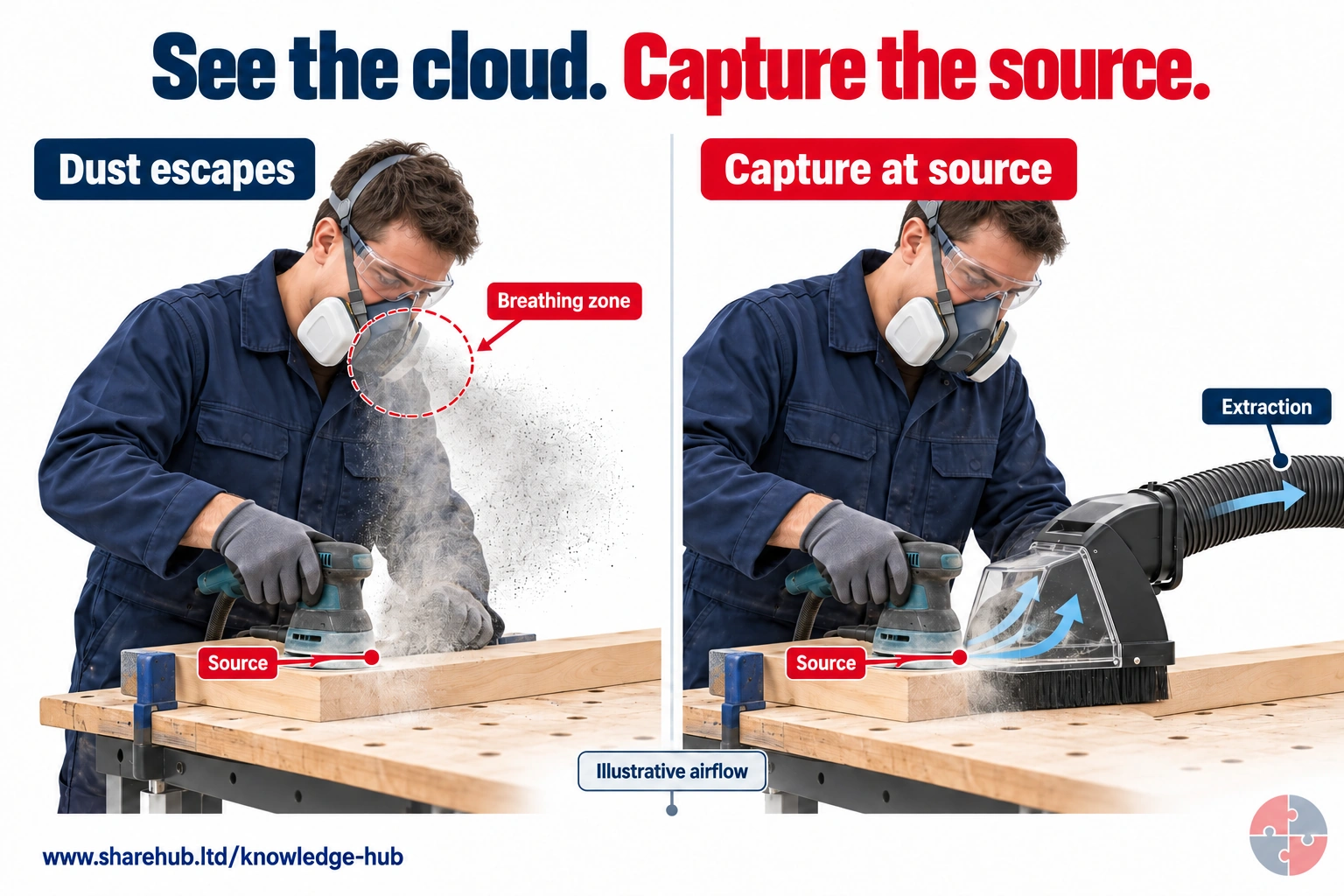
The paired sanding scenes make an otherwise hard-to-see dust release visible as a conceptual cloud. In the second view, extraction draws contamination away from the breathing zone. The task must still be assessed for the material and residual exposure.
Why is visible dust not the whole exposure?
Fine airborne dust may be difficult to see. Capture needs a competent design and evidence of effective control.
Conceptual airflow, not a measurement or proof of LEV performance.
Source guidance: HSE guidance
The health logic is simple but powerful: airborne contaminants can reach the lungs, bloodstream, eyes and skin. Some cause immediate irritation; others cause asthma, cancer, chronic lung disease, metal fume fever, sensitisation, poisoning or long-latency disease. LEV reduces the dose by removing the contaminant at the point where it is easiest to control.
For Diploma-level understanding, LEV should be linked to exposure route, dose, duration, substance hazardous properties and the reliability of controls. A short job with a low-toxicity nuisance dust is not the same as repeated spraying of respiratory sensitisers or machining hardwood dust.
| Health concern | LEV control logic | Example |
|---|---|---|
| Occupational asthma | Capture sensitising mist, fume or dust before inhalation. | Isocyanate spray mist, flour dust, wood dust. |
| Cancer risk | Reduce exposure to carcinogenic dusts or fumes. | Hardwood dust, silica dust, welding fume, chromium VI. |
| Irritation and acute effects | Prevent short-term peaks and visible clouds. | Acid mist, solvent vapour, solder fume. |
| Chronic lung disease | Reduce repeated inhalation exposure over working life. | Construction dust, welding fume, mineral dust. |
| Systemic toxicity | Limit inhaled vapours or particles that affect organs. | Lead, manganese, solvents, formaldehyde. |
Which contaminants can LEV control?
LEV can control many airborne forms, but the design must match the contaminant and how it is generated.
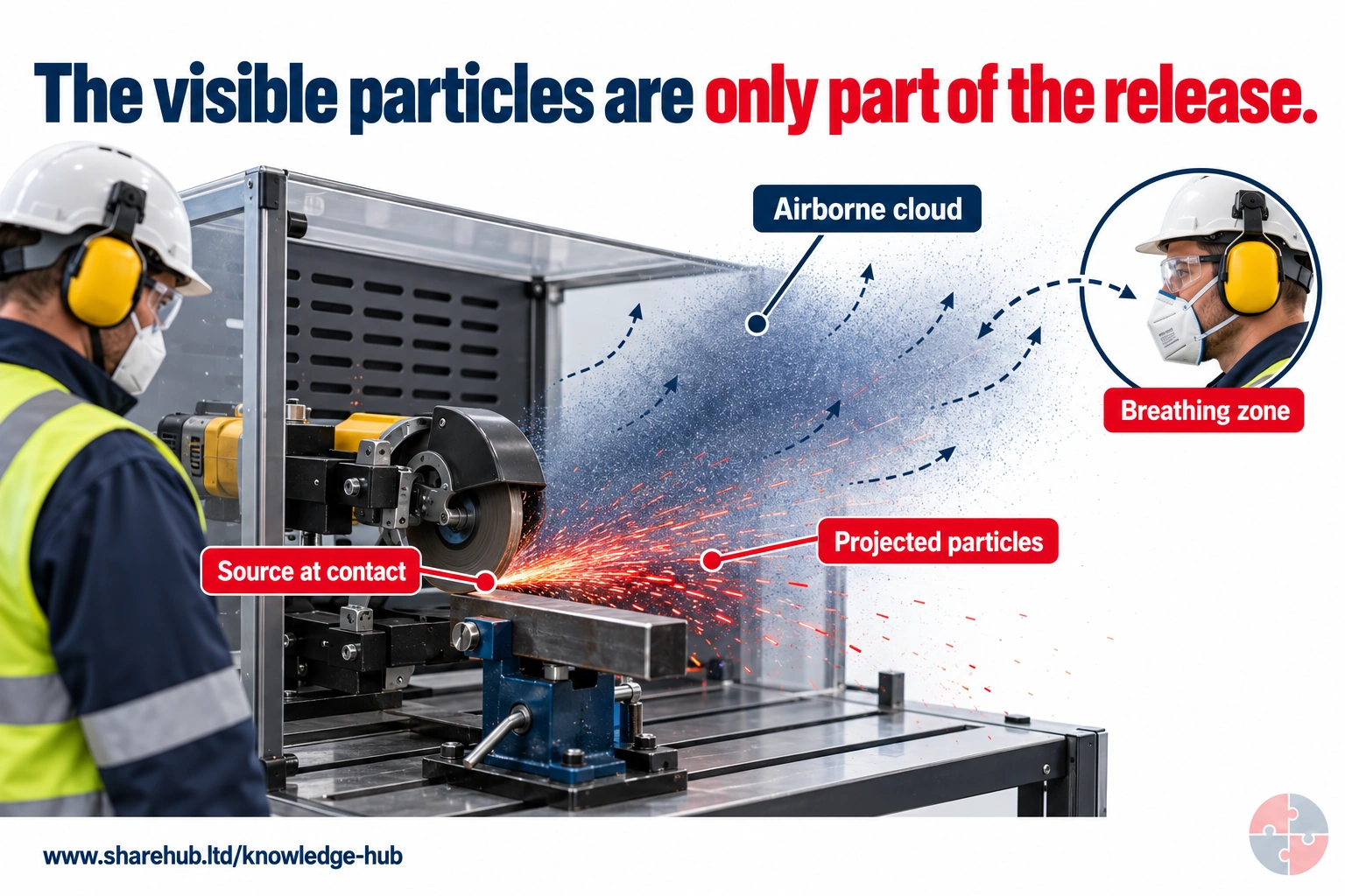
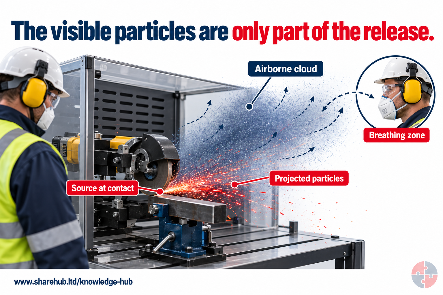
Grinding can generate a directional release and an airborne contaminant cloud. The more visible projected particles do not describe the whole inhalation exposure.
What must be understood before choosing a capture hood?
The source location, direction and momentum of the cloud, work position and breathing zone—not just the visible sparks or particles.
Conceptual contaminant cloud, not measured exposure or a validated grinder-control arrangement. The visible PPE is illustrative and does not establish adequate respiratory or other protection.
Source guidance: HSE HSG258
A common weak answer is to say 'fit extraction'. A stronger answer asks what form the contaminant takes, how fast it is emitted, whether it is hot, wet, sticky, flammable, explosive, toxic, corrosive, fibrous, respirable or visible, and how the task is actually performed.
Dust behaves differently from solvent vapour; welding fume behaves differently from spray mist; a heavy particle thrown from a grinder needs a different hood position from a vapour rising from a warm tank. The contaminant form drives hood choice, capture velocity, duct transport velocity, air cleaner selection, discharge route and maintenance burden.
| Contaminant form | Typical examples | LEV implication |
|---|---|---|
| Dust | Wood dust, silica, flour, cement, powders. | Capture near source, maintain transport velocity and manage filter loading. |
| Fume | Welding fume, solder fume, hot metal fume. | Capture at plume/source; consider visibility, heat and operator position. |
| Mist/aerosol | Isocyanate spray mist, metalworking fluid mist. | Enclosure, spray booth/room, filtration and clearance time may matter. |
| Vapour | Solvents, paints, degreasers, adhesives. | Safe discharge, no inappropriate recirculation, Dangerous Substances and Explosive Atmospheres Regulations (DSEAR) review where flammable. |
| Gas | Process gases, acidic gases, ammonia-type releases. | Specialist containment, gas detection, emergency and discharge assessment. |
| Fibres | Asbestos and fibrous materials where specialist rules apply. | Use specialist asbestos controls; ordinary LEV is not enough for licensed asbestos work. |
Where is LEV used in real workplaces?
LEV appears in many sectors, but each application has a different control standard and failure route.
LEV can be built into tools, benches, booths, fume cupboards, enclosures, welding arms, process vessels, hoppers, glove boxes and mobile extraction units. The learner should focus on the relationship between the source and hood, not the size of the kit.
A small on-tool sander can be excellent if it captures at source and the extractor/filter is maintained. A large shiny booth can be poor if filters are blocked, airflow is unbalanced, clearance time is unknown or the operator removes air-fed BA too early.
| Application | Contaminant | What good control looks like |
|---|---|---|
| Accident repair spray booth | Isocyanate paint mist and solvent vapour. | Enclosed booth/room, measured clearance time, air-fed BA and health surveillance. |
| Body filler sanding | Fine dust and possible sensitising/irritant dust. | On-tool extraction, compatible sander shroud and filter maintenance. |
| Welding bay | Metal fume and gases. | Correctly positioned extraction, capture check and RPE where needed. |
| Woodworking machine | Wood dust and chips. | Machine-integrated extraction and dust collector maintenance. |
| Laboratory fume cupboard | Vapours, fumes or aerosols. | Face velocity/containment checks and sash discipline. |
| Powder tipping | Dust cloud during transfer. | Enclosure or receiving hood, low drop height and clean-up controls. |
| Grinding or cutting | Dust, sparks, metal particles or silica. | Correct hood/shroud, spark/fire assessment and filter cleaning. |
How can the hierarchy of controls reduce airborne exposure before relying on local exhaust ventilation?
LEV is an engineering control after elimination and substitution have been considered; the actual task still needs verification.
HSE HSG258 treats the hood, source, worker and airflow as one system. For a body-filler sanding task, ERICPD below links the five-level hierarchy to the owner and failure decision. A capture test should observe the actual sanding position and cross-draught, not only a fan reading.
If the contaminant crosses the breathing zone or the tool position changes beyond the designed capture zone, stop sanding, adjust the method and verify capture before restart. RPE may be needed for residual exposure but does not repair a failed source control.
How can the ERICPD hierarchy of controls reduce airborne exposure before relying on local exhaust ventilation?

| ERICPD | Five-level hierarchy | Sanding-task choice | Owner, proof and stop |
|---|---|---|---|
| Eliminate | Elimination | Buy prefinished parts or avoid dusty cutting/sanding where feasible. | Process owner checks feasibility; undocumented process change holds work. |
| Reduce | Substitution | Use a lower-dust product and less dust-generating tool/method. | COSHH assessor checks product and process; new material triggers review. |
| Isolate / Control | Engineering controls | Fit task-specified on-tool extraction/LEV, enclose or separate the emission, and provide make-up air. | LEV designer commissions capture under real task conditions; escape stops work. |
| Control | Administrative controls | Position hood/tool correctly, check airflow indicator, clean safely and maintain filters. | User pre-use check plus supervisor observation; alarm or damaged hose stops work. |
| PPE | PPE | Provide suitable RPE and other protection for remaining exposure. | Competent selector checks fit and condition; failed RPE stops exposure work. |
| Discipline | Sustaining all levels | Investigate defects, compare TExT to commissioning, act on worker reports and retest changes. | Manager closes defects and verifies a later shift; recurring failure triggers redesign. |
How can the ISO 45001 hierarchy of controls reduce airborne exposure before relying on local exhaust ventilation?

| ERICPD | Five-level hierarchy | Sanding-task choice | Owner, proof and stop |
|---|---|---|---|
| Eliminate | Elimination | Buy prefinished parts or avoid dusty cutting/sanding where feasible. | Process owner checks feasibility; undocumented process change holds work. |
| Reduce | Substitution | Use a lower-dust product and less dust-generating tool/method. | COSHH assessor checks product and process; new material triggers review. |
| Isolate / Control | Engineering controls | Fit task-specified on-tool extraction/LEV, enclose or separate the emission, and provide make-up air. | LEV designer commissions capture under real task conditions; escape stops work. |
| Control | Administrative controls | Position hood/tool correctly, check airflow indicator, clean safely and maintain filters. | User pre-use check plus supervisor observation; alarm or damaged hose stops work. |
| PPE | PPE | Provide suitable RPE and other protection for remaining exposure. | Competent selector checks fit and condition; failed RPE stops exposure work. |
| Discipline | Sustaining all levels | Investigate defects, compare TExT to commissioning, act on worker reports and retest changes. | Manager closes defects and verifies a later shift; recurring failure triggers redesign. |
What parts make up an LEV system?
A complete LEV system is an airflow chain; weakness in one part weakens the whole control.
2 related visuals
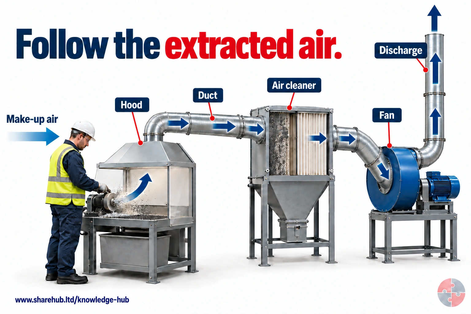
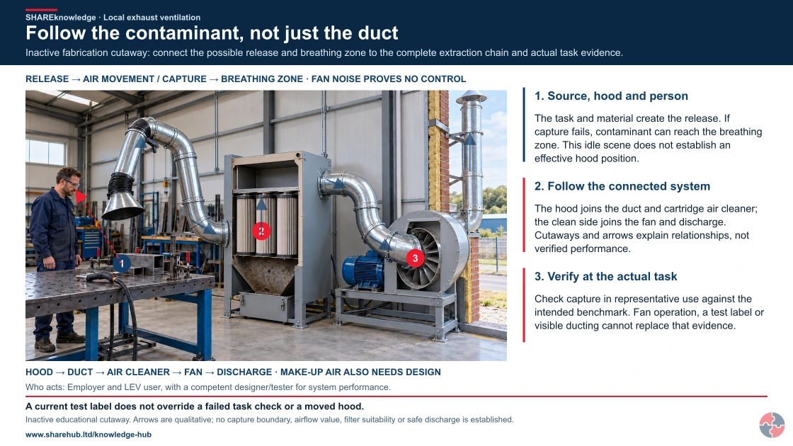
Follow the indicated flow from the source into the hood, through the duct and air cleaner, into the centrifugal fan and up the discharge stack. The motor is outside the illustrated air path. Replacement air must support extraction without introducing disruptive draughts.
What could happen if replacement air is ignored?
Poor make-up air arrangements can disrupt intended extraction and create unwanted airflow patterns; system performance must be checked.
Conceptual system sequence, not an LEV design. Fan location, air cleaning, make-up air, discharge and machinery safeguards need competent design and commissioning.
Source guidance: HSE HSG258
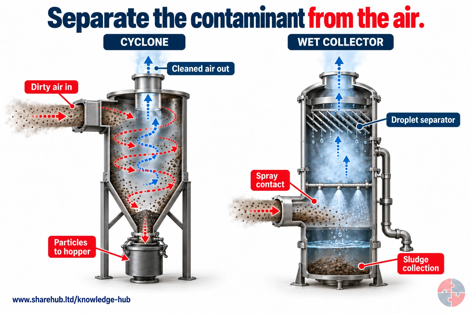
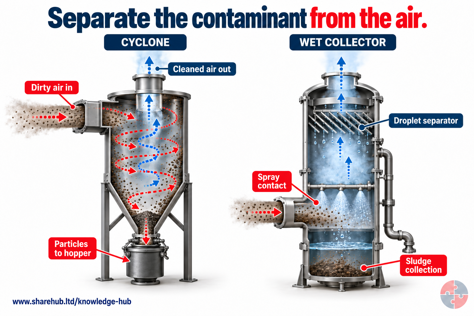
The cyclone uses swirling motion to separate particles into a hopper. The wet collector brings contaminants into liquid contact, then separates droplets and manages contaminated liquid or sludge.
Why does the wet collector need a droplet separator?
It helps keep liquid droplets from being carried out with the cleaned air; collected liquid and sludge still need controlled handling.
Generic separation principles; contaminant compatibility, collection efficiency and waste arrangements require technical design.
Source guidance: HSE HSG258
The visible hood is only the beginning. The system includes ducts, bends, dampers, air cleaners, filters, fans, stacks, make-up air and monitoring devices. It may also include the machine guard, spray booth structure, interlocks, pressure indicators, filter alarms, airflow gauges and operating method.
A professional review follows the air path from contaminant source to safe discharge. It asks whether enough air reaches the hood, whether the duct carries contaminant without settling, whether the filter or collector is suitable, whether the fan can overcome system resistance, and whether discharge could expose other people or re-enter the building.
| Component | Purpose | Common failure |
|---|---|---|
| Hood or enclosure | Captures or contains contaminant. | Too far away, wrong shape, damaged, obstructed or poorly used. |
| Ductwork | Carries contaminated air away. | Leaks, blockages, crushed flexible duct or poor bends. |
| Air cleaner/filter | Removes particles, mist or vapour where needed. | Blocked filters, wrong media or poor disposal of waste. |
| Fan/air mover | Creates airflow through the system. | Wrong rotation, worn fan, belt slip or insufficient duty. |
| Discharge | Releases air safely. | Discharge near doors, windows, intakes or occupied areas. |
| Make-up air | Replaces extracted air. | Room becomes starved, draughty or process airflow is disrupted. |
| Indicator/instrument | Shows whether performance is within expected range. | Gauge absent, ignored, uncalibrated or not understood. |
What is the LEV system journey from source to assurance?
The easiest way to understand LEV is to follow the contaminant and then follow the evidence.
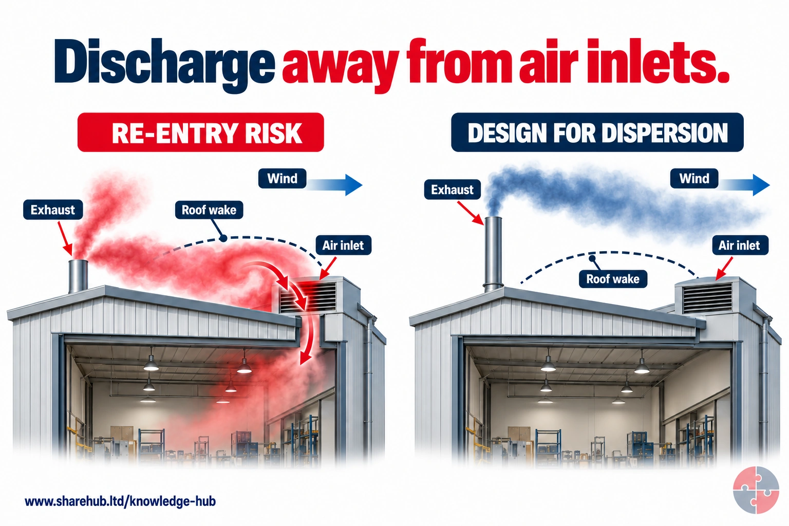
Discharged contaminant can re-enter through nearby inlets when stack location and building wake are poorly considered. The comparison shows the design questions rather than a universal height rule.
What must be considered as well as stack height?
Discharge velocity and direction, building geometry, wind effects, contaminant properties and nearby air inlets or buildings.
Conceptual dispersion, not a site-specific stack design or measured plume.
Source guidance: HSE HSG258
The contaminant journey starts at the task. A sanding disc, spray gun, welding arc or powder transfer creates dust, fume, mist, vapour or gas. The hood or enclosure must capture or contain that contaminant before it reaches the breathing zone. Ductwork must then carry it without leakage or settling. The air cleaner or filter must remove what it is designed to remove. The fan must maintain the required airflow. The discharge must release air safely, and the monitoring, maintenance and examination arrangements must prove the control is still working.
For learners, this journey is a useful mental model because it prevents the common mistake of treating LEV as a single item. If any stage in the journey is weak, the system can still look present while exposure control has failed.
1. Contaminant source
Identify exactly where dust, fume, mist, vapour or gas is generated and how it moves.
2. Hood or enclosure
Capture or contain the contaminant before it enters the worker's breathing zone.
3. Duct and air cleaner
Move contaminated air through ductwork and remove particles, mist or vapour where required.
4. Fan and discharge
Maintain the required airflow and release cleaned or extracted air to a safe location.
5. Monitoring
Use gauges, indicators, visual checks, exposure data and health surveillance to detect weak control.
6. Maintenance and TExT
Keep performance reliable through checks, repair, statutory thorough examination and closed defects.
| Journey stage | Key question | Evidence expected |
|---|---|---|
| Contaminant source | What is generated and how hazardous is it? | COSHH assessment, safety data sheet (SDS), WEL review and process observation. |
| Hood | Is the contaminant captured before it crosses the breathing zone? | Commissioning evidence, smoke/dust-lamp checks and user observation. |
| Duct | Is airflow carrying contaminant without leakage, damage or settlement? | Duct inspection, pressure readings and maintenance records. |
| Filter or air cleaner | Is the cleaner suitable and not overloaded? | Filter change record, differential pressure and waste controls. |
| Fan | Can the fan overcome system resistance and maintain duty? | Fan inspection, belt/bearing checks and measured performance. |
| Discharge | Could extracted air re-enter or expose others? | Discharge location review and environmental/DSEAR assessment where relevant. |
| Monitoring and assurance | Do routine checks, TExT, exposure results and health surveillance tell the same story? | Dashboard, TExT close-out, monitoring interpretation and management review. |
What does the LEV control chain look like as a schematic?
The schematic is a practical learning map: follow the contaminant forward, then follow the assurance evidence back.
A useful LEV schematic should not stop at the fan. The control chain begins with the contaminant source and ends only when monitoring, maintenance and health evidence show the control is still reliable. That is why a Diploma-level answer should describe the physical airflow path and the management evidence path together.
This simple visual flow can be used during teaching, inspections and TExT review. Start at the task and ask whether the contaminant is captured before the breathing zone. Then follow the duct, filter, fan and discharge. Finally, follow the evidence backwards: are the checks, monitoring, maintenance and user behaviours strong enough to prove the system still protects people?
Contaminant source
Dust, fume, mist, vapour or gas is generated by sanding, spraying, welding, tipping, grinding or mixing.
Hood or enclosure
The source is captured or contained before the cloud crosses the worker's breathing zone.
Duct and air cleaner
Contaminated air is carried through ductwork and cleaned or filtered where required.
Fan and discharge
The fan maintains the design airflow and discharge is routed so it does not re-enter or expose others.
Indicators and checks
Users confirm expected airflow, pressure or warning indicators before relying on the system.
Maintenance, TExT and learning
Defects, exposure results and health surveillance signals are reviewed and closed out.
| Flow stage | Schematic question | Common failure to challenge |
|---|---|---|
| Source | Where exactly is the contaminant created? | Assessment names the substance but not the task emission point. |
| Capture | Does airflow pull the cloud away from the breathing zone? | Worker stands between source and hood. |
| Transport | Can ducts carry contaminant without leakage or settlement? | Crushed hose, blocked duct or poor transport velocity. |
| Cleaning | Is the filter or air cleaner suited to the contaminant? | Wrong filter, overloaded collector or unsafe waste handling. |
| Air movement | Does the fan maintain the benchmark performance? | Belt slip, worn fan, wrong damper position or poor make-up air. |
| Discharge | Could extracted air re-enter or expose others? | Stack near intake, door, window or occupied area. |
| Assurance | Do checks, TExT, monitoring and health data agree? | Certificate filed but defects, symptoms or high results ignored. |
What hood types should learners understand?
Hood selection is often the difference between good exposure control and expensive theatre.
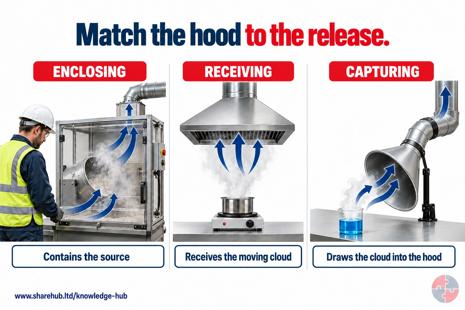
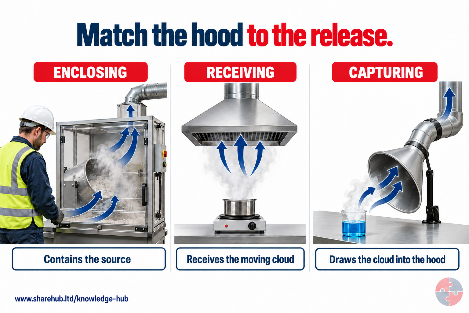
Enclosing hoods contain a source; receiving hoods intercept a cloud already moving towards them; capturing hoods draw a nearby external cloud into extraction.
Why can a distant capturing hood fail even though the fan runs?
The hood may not generate sufficient capture airflow at the source; cloud direction, distance and disturbance matter.
Conceptual hood categories; actual control needs source-specific design and verified performance.
Source guidance: HSE HSG258
HSG258 describes different hood approaches. Enclosing hoods surround the source and usually provide the best control. Receiving hoods use the natural direction of the contaminant cloud, such as a hot plume or a particle stream. Capturing hoods have to pull contaminant into the hood where the source is open.
The further a capturing hood is from the source, the harder it becomes to control exposure. Airflow falls rapidly with distance, and small draughts can overpower weak capture. That is why hood position, side panels, flanges, operator position and task layout matter as much as fan size.
| Hood type | How it works | Example |
|---|---|---|
| Full enclosure | Surrounds the source and separates people from contaminant. | Glove box, enclosed automated process. |
| Room enclosure | Contains the process and sometimes the operator. | Spray booth or abrasive blasting booth. |
| Partial enclosure | Surrounds much of the source but has an open face. | Fume cupboard, walk-in spray room, enclosure with access opening. |
| Receiving hood | Receives contaminant moving naturally in a predictable direction. | Canopy over hot process, hood in grinding particle path. |
| Capturing hood | Draws contaminant into the hood from an open source. | Welding arm, rim extraction, downdraught bench. |
| On-tool extraction | Captures dust at the tool interface. | Sander, grinder, saw or drill extraction shroud. |
What are capture zones, working zones and breathing zones?
The most important practical question is whether the contaminant is captured before it crosses the breathing zone.
Follow the contaminant, not just the duct
Full written explanation
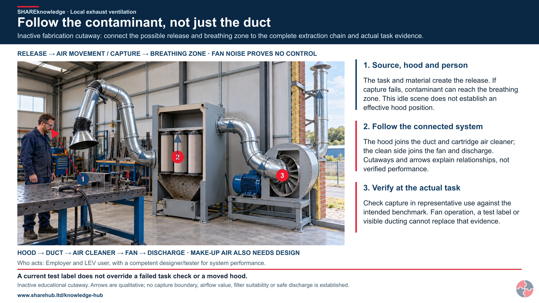
A detailed realistic fabrication-workshop cutaway keeps the cold clamped workpiece, resting welding torch, worker, offset capture hood, joined duct, cartridge air cleaner, centrifugal fan and outside discharge in one connected physical view. The hood duct enters the lower dirty chamber outside the cartridges; the cartridge-top tube-sheet separates it from the upper clean plenum. A separate upper clean-side duct joins the central axial fan inlet; the motor remains outside the air path and the tangential fan outlet joins the discharge stack. Native short arrows qualitatively trace that component path. A separate dashed red arrow shows a potential release-to-breathing-zone relationship if capture fails; it is not an observed emission, measured airflow or proof of hood performance. All tools and equipment are inactive, and the openings in the cabinet/fan/building are teaching sections, not permission to remove safeguards. Native labels retain the release, cloud movement and breathing-zone mechanism while connecting the whole system to actual capture evidence. Make-up air, filter compatibility, discharge location, machinery safeguards and commissioning require competent design and verification. The image supplies no measured capture envelope, hood distance, airflow/pressure value, filter specification, exposure level, operating method or system approval. The original complete controls, analytical charts, labelled equipment visuals, native models/course controls, formal testing and GB/NI source distinctions remain unchanged.
Inactive fabrication cutaway: connect the possible release and breathing zone to the complete extraction chain and actual task evidence.
- Contaminant released. The tool, material and work position determine the release.
- Cloud moves through the work. Hood position, body position and cross-draughts can disrupt capture.
- Breathing zone reached. Contaminant can be inhaled even though a fan is running.
Change the pathway
- Reduce the release. Change or contain the process where practicable.
- Capture at the source. Use the correct hood and position the work within its effective working zone.
- Verify performance. Use suitable indicators, task checks, maintenance and required examination/testing.
Evidence check: A current test label does not override a failed task check or a moved hood.
Primary references: HSE: LEV commissioning and intended-performance benchmarks (GB) · HSE: LEV indicators, competence, testing and on-tool checks (GB) · HSE HSG258: controlling airborne contaminants (GB)
Open the complete HD image (new tab)Download image
Primary references: HSE: LEV commissioning and intended-performance benchmarks (GB) · HSE: LEV indicators, competence, testing and on-tool checks (GB) · HSE HSG258: controlling airborne contaminants (GB)
2 related visuals
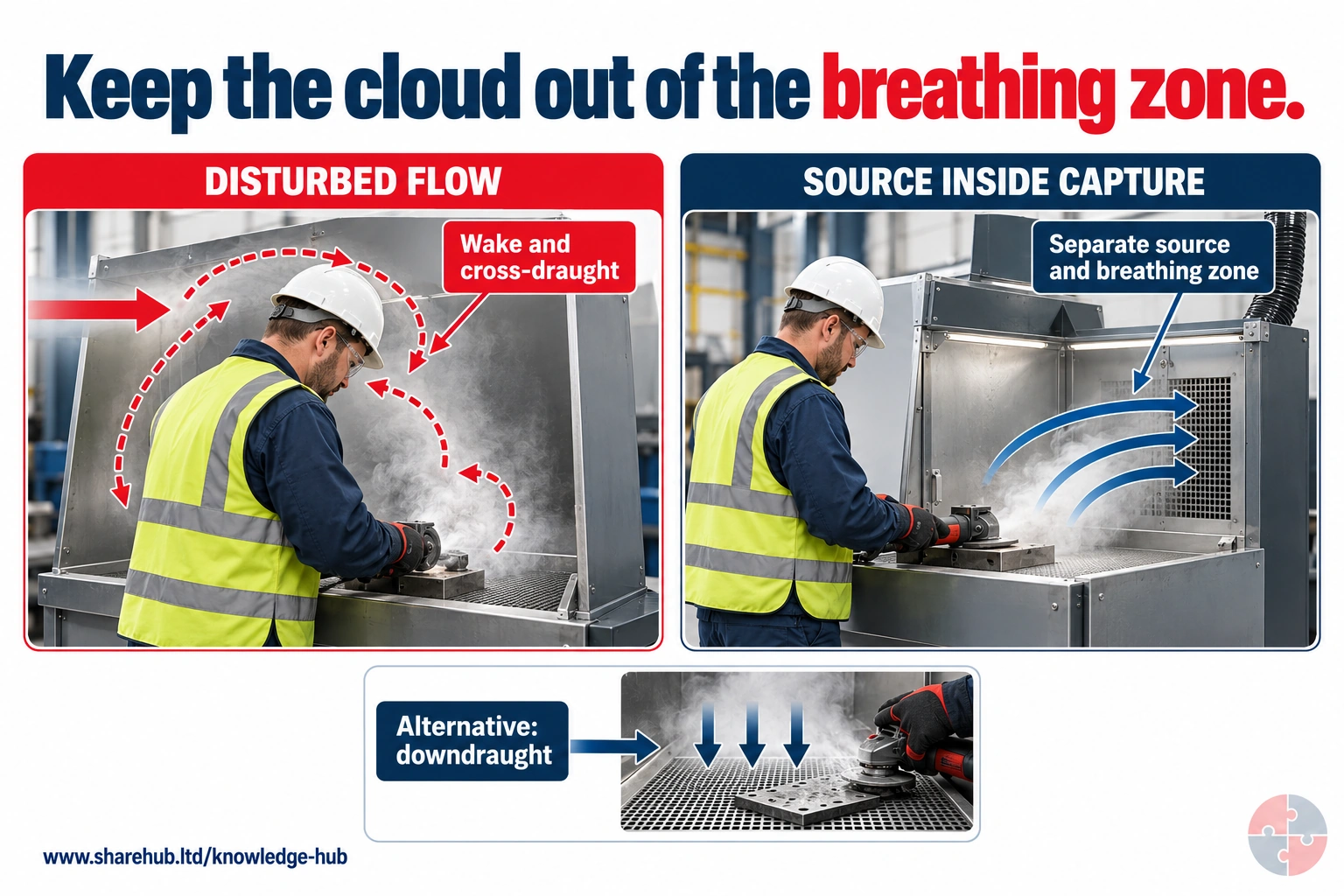
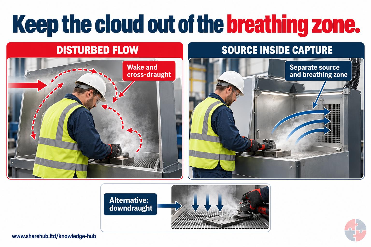
The operator's body and cross-draughts can disrupt airflow near an enclosure opening. Source position and alternative extraction arrangements can reduce the chance of a cloud passing through the breathing zone.
What should be checked after moving the source inward?
Confirm the actual work remains within effective capture, with representative movement and draughts considered.
Conceptual airflow paths; smoke tests or other competent performance checks must verify actual conditions.
Source guidance: HSE HSG258
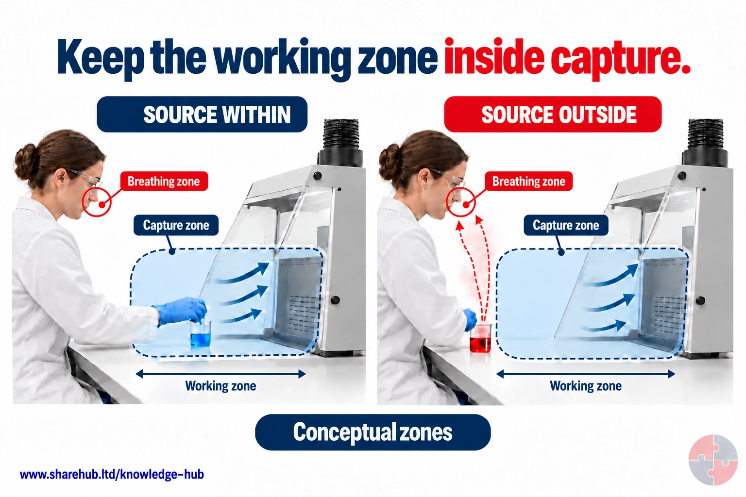
Both hoods show the same blue capture envelope. The left-hand beaker is inside it; the right-hand beaker has moved towards the bench edge and outside capture, allowing vapour to escape towards the breathing zone. Keep contaminant-generating work within verified capture.
What changed while the blue capture zones stayed the same?
The source position changed: the right-hand beaker was moved towards the operator and beyond the blue capture area. The comparison shows why source position matters, without reducing the capture zone in the outside example.
Envelopes, coloured liquids and airflow arrows are teaching geometry. They are not measured boundaries, chemical identities or a performance certificate.
Source guidance: HSE HSG258
The capture zone is the area where the hood has enough influence to pull contaminant into the system. The working zone is where the task is performed. The breathing zone is the air the worker inhales. Good design keeps the contaminant path away from the breathing zone and into the hood.
Common failures are painfully simple: the worker leans over the source, the hood is placed behind the worker, a cross-draught blows mist away from the booth face, the extraction arm is not moved with the weld, or a car body in a spray booth creates eddies and dead zones.
| Situation | What can go wrong | Better control |
|---|---|---|
| Worker between source and hood | Contaminated air passes through breathing zone. | Move hood/source/worker so airflow travels away from the face. |
| Extraction arm too far away | Capture velocity too weak at the source. | Position hood close enough and train users to move it. |
| Door or fan draught | Crossflow defeats hood capture. | Control room airflow and locate process away from draughts. |
| Large object in booth | Vehicle body creates eddies and stagnant zones. | Confirm booth airflow and clearance under normal conditions. |
| On-tool hose crushed | Capture collapses despite tool being connected. | Check hose, filter and airflow before work starts. |
What airflow concepts matter for Diploma-level understanding?
Learners do not need to become ventilation designers, but they should understand the key measurements and why they matter.
2 related visuals
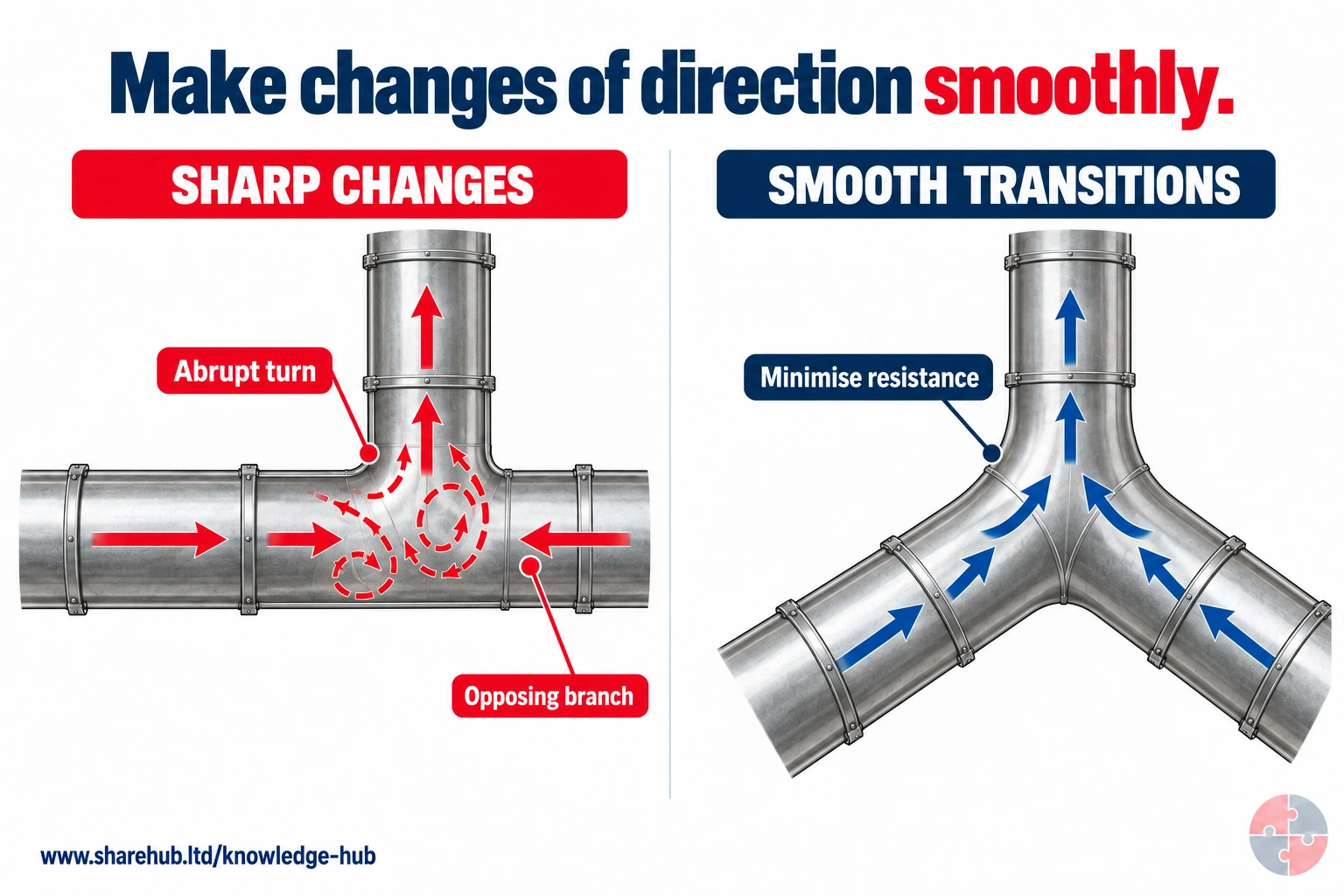
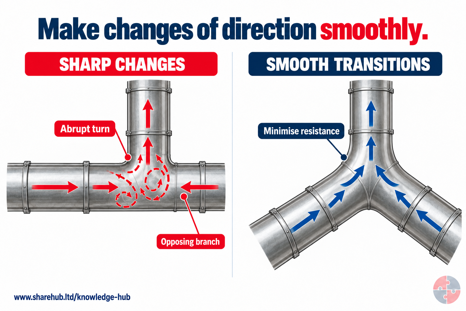
Bends, junctions and section changes add resistance. Smooth transitions and simpler routing can reduce avoidable losses, while conveying velocity and system balance still need design checks.
Why is a sharp T-junction a concern?
It can create abrupt opposing flow and greater resistance compared with a properly designed gradual junction.
Qualitative duct comparison; no pressure-loss value, transport velocity or final design is implied.
Source guidance: HSE HSG258
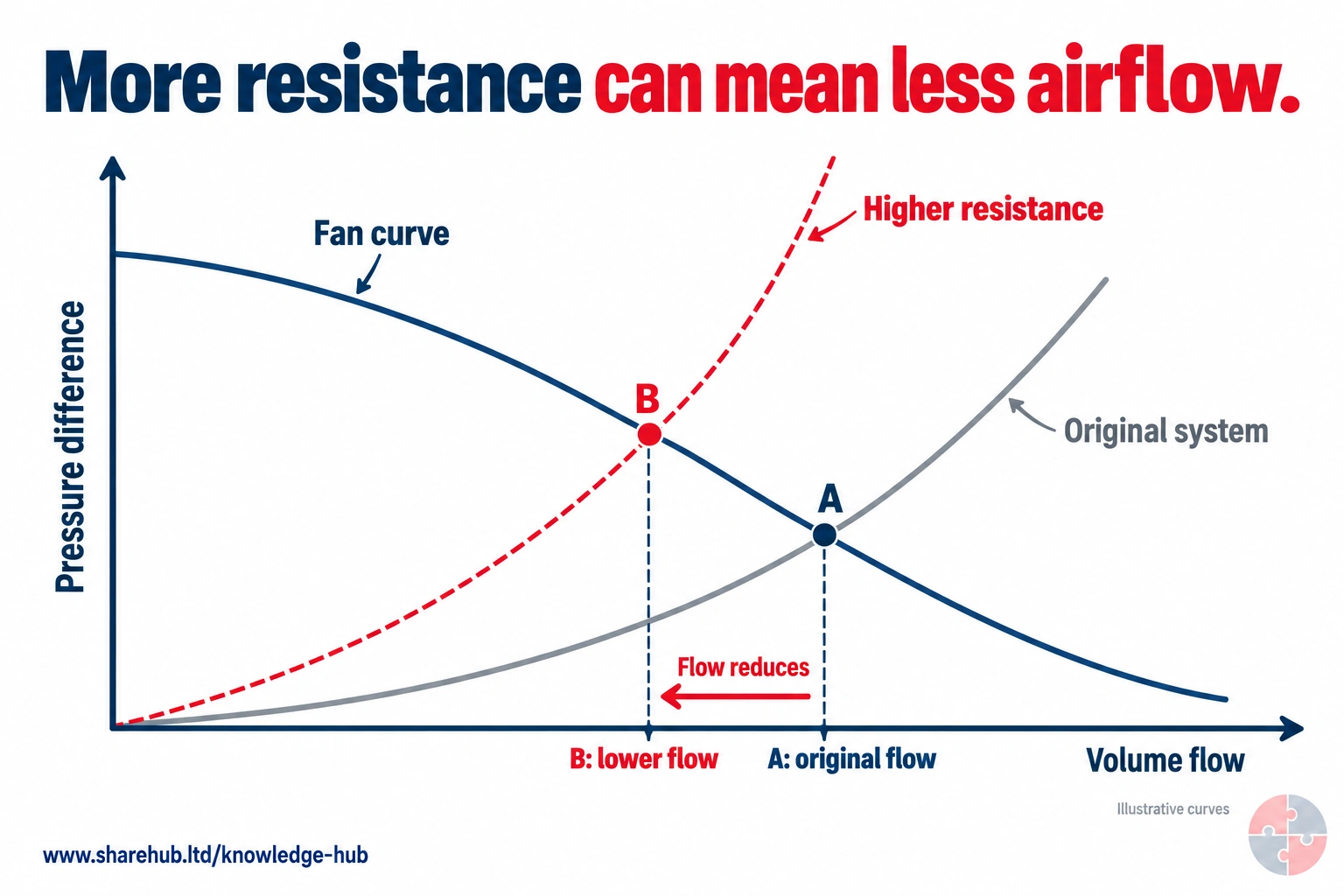
With a fixed fan characteristic, increasing system resistance moves the operating point to a lower flow and a higher pressure difference in the illustrated stable region.
What moves if resistance increases but the fan curve stays the same?
The intersection moves along the fan curve towards lower flow. Actual fan/system performance must be established for the equipment.
Illustrative curves without units or test data; they are not manufacturer performance information.
Source guidance: HSE HSG258
Airflow is not just 'more suck'. Too little airflow fails to capture contaminant; too much can disturb the process, waste energy, create noise, affect spray finish or pull material into filters unnecessarily. The designer needs enough airflow at the right place, in the right direction and through a system that can maintain transport and filtration.
Measurements such as face velocity, capture velocity, transport velocity, static pressure and volumetric flow help prove performance. They are most useful when compared with commissioning data or an agreed performance standard, not as isolated numbers.
| Concept | Meaning | Why it matters |
|---|---|---|
| Capture velocity | Air speed needed at the source to draw contaminant into the hood. | Too low means the cloud escapes into the breathing zone. |
| Face velocity | Air speed across an opening such as a fume cupboard or booth face. | Helps assess containment at open faces. |
| Transport velocity | Air speed in ducts needed to carry particles or mist without settling. | Too low can block ducts; too high can increase wear/noise. |
| Static pressure | Pressure condition used to understand system resistance and performance. | Useful for comparing fan, filter and duct performance over time. |
| Volumetric flow rate | Total volume of air moved per unit time. | Needed to confirm design flow and air change in enclosures. |
| Make-up air | Replacement air entering the workplace. | Without it, extraction performance and comfort may deteriorate. |
| Pressure differential | Difference between spaces or across filters. | Helps identify filter loading, leakage or booth balance. |
How should LEV be specified before buying or changing it?
A good specification describes the contaminant and task before asking for equipment.
Many LEV failures are procurement failures. A supplier cannot design a credible system if the employer only asks for 'extraction'. The specification should describe the process, contaminant, hazardous properties, emission point, task frequency, quantities, worker position, workspace, draughts, cleaning method, WELs, fire/explosion issues, environmental discharge, maintenance access and future changes.
For an accident repair centre, the specification for a spray booth or room should include vehicle size, spray products, isocyanate use, air-fed BA arrangements, booth mode, bake cycle, filter loading, clearance time, monitoring, access control, fire/DSEAR issues and how people will know when it is safe to remove BA or enter.
| Prompt | Why it matters | Evidence to provide |
|---|---|---|
| What contaminant is generated? | Hazard properties drive control standard. | SDS, COSHH assessment, WEL and task description. |
| How is it generated? | Spraying, sanding, heating, cutting and tipping create different clouds. | Process observation and photos/video where useful. |
| Where is the worker? | Breathing-zone relationship drives hood design. | Task layout and ergonomic review. |
| How often and how long? | Duty affects exposure and maintenance. | Production pattern and task duration. |
| What else affects airflow? | Draughts, make-up air, doors and objects can defeat capture. | Room layout and ventilation review. |
| What proof is required? | Commissioning and exposure checks must be planned up front. | Performance specification and acceptance criteria. |
| What legal/external issues apply? | DSEAR, environmental discharge or health surveillance may apply. | DSEAR/environmental/occupational health (OH) review. |
What should commissioning prove?
Commissioning proves that the installed LEV achieves the intended control performance before it becomes routine work equipment.
Commissioning is the baseline for future control. It should be done under realistic conditions, with the process operating as it will be used. It should confirm installation, airflow, pressures, capture or containment, hood position, filter performance, alarms/indicators, discharge, user information and whether exposure is adequately controlled.
Without commissioning data, future thorough examinations are weaker because the examiner has no original performance benchmark. After major changes to process, materials, layout, hood, ducting, fan, filters, booth arrangement or work method, recommissioning may be needed.
HSE commissioning guidance expects the supplier to demonstrate the intended control in use and provide a commissioning report. Define the contaminant, hood position, worker movement, process rate and worst credible operating condition before acceptance; save the measured benchmark for future examinations.
| Commissioning element | What it proves | Why it matters later |
|---|---|---|
| Installation check | The system matches design and drawings. | Prevents hidden defects from becoming normal. |
| Airflow and pressure measurements | The system reaches performance targets. | Creates benchmark for TExT and maintenance. |
| Capture/containment demonstration | The contaminant goes into the hood/enclosure. | Shows real control, not just airflow. |
| Smoke/dust lamp/visual test | Reveals leakage, eddies and dead spots. | Helps train users and refine layout. |
| Exposure monitoring where needed | Confirms adequate control for high-risk substances. | Links engineering control to health protection. |
| User training and handover | Workers know how to use and check the system. | Prevents misuse from day one. |
| Commissioning report | Records intended operating performance. | Becomes the comparison point for future tests. |
How do commissioning, daily checks and TExT differ?
Commissioning, daily checks and TExT are connected, but they answer different assurance questions.
Learners often confuse commissioning and TExT because both can involve measurements, smoke testing, airflow checks and reports. The distinction matters. Commissioning is the proof that the installed or modified system meets the intended control specification before people rely on it. Daily and routine checks are the user's first-line confirmation that the system appears ready for work. TExT is the competent periodic examination that checks whether the LEV remains effective over time.
A strong management system joins all three together. The commissioning report sets the benchmark. Daily checks spot obvious deterioration. Maintenance keeps the system within the expected range. TExT compares current performance with the benchmark, identifies defects and confirms whether exposure control is still adequate. Managers then make sure defects are closed, not just filed.
| Assurance activity | When it happens | What it proves | Typical evidence |
|---|---|---|---|
| Commissioning | When LEV is installed, significantly modified, recommissioned or accepted into use. | The system is suitable for the process and controls exposure under intended operating conditions. | Commissioning report, design data, airflow/pressure measurements, capture demonstration, user manual and logbook. |
| Daily/user checks | Before use and during routine work, with frequency matched to risk and use. | The LEV is likely to be available and working before the task starts. | Closed-question checklist, airflow indicator in range, hood position check, filter/alarm check and defect report. |
| Planned maintenance | At intervals based on manufacturer guidance, contamination, wear and site experience. | Wear, filter loading and equipment deterioration are controlled before performance drops. | Maintenance schedule, repair records, filter changes, fan/belt checks and contaminated-maintenance controls. |
| TExT | At least every 14 months for most LEV, and more often where law, risk or wear requires it. | The system remains effective over time and still meets intended performance. | Competent examiner report, measured data, comparison with commissioning benchmark, defect grading and next due date. |
| Management review | After TExT defects, monitoring results, health surveillance concerns, incidents or process change. | The business has understood the evidence and improved the control. | Action tracker, risk register update, exposure review, training refresh and close-out verification. |
What should the user manual and logbook contain?
The user manual explains how the LEV should work; the logbook proves it is checked, maintained and repaired.
HSE's simple LEV guidance emphasises that employers should receive a user manual, logbook and commissioning report. These documents are not decorative. They tell the business how the system controls exposure, what performance looks like, how users should work with it, what checks are needed, which parts need replacement and when statutory examination is due.
The logbook should record checks, maintenance, replacement filters, repairs, deviations, faults, examiner reports and corrective actions. It should be useful enough that a supervisor can answer: did this LEV protect people this week?
| Document | Should contain | Quality test |
|---|---|---|
| User manual | System description, diagrams, design purpose, controls and correct use. | Can a new supervisor explain how the system protects people? |
| Performance data | Airflows, pressures, velocities, test points and control benchmarks. | Can TExT compare current performance with intended performance? |
| Maintenance schedule | Filter changes, cleaning, inspection and replacement intervals. | Are frequencies realistic for the process and contaminant? |
| Signs of failure | What operators should notice and report. | Are warning signs written in plain workplace language? |
| Logbook | Checks, maintenance, repairs, replacements and actions. | Are faults closed, not just recorded? |
| Commissioning report | Initial proof that LEV works as designed. | Is it available to the examiner and manager? |
What daily and routine checks should users carry out?
Routine checks catch obvious deterioration between formal tests.
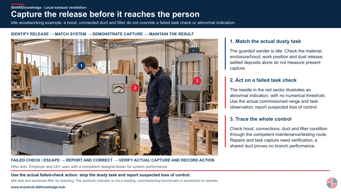
Capture the release before it reaches the person
Full written explanation
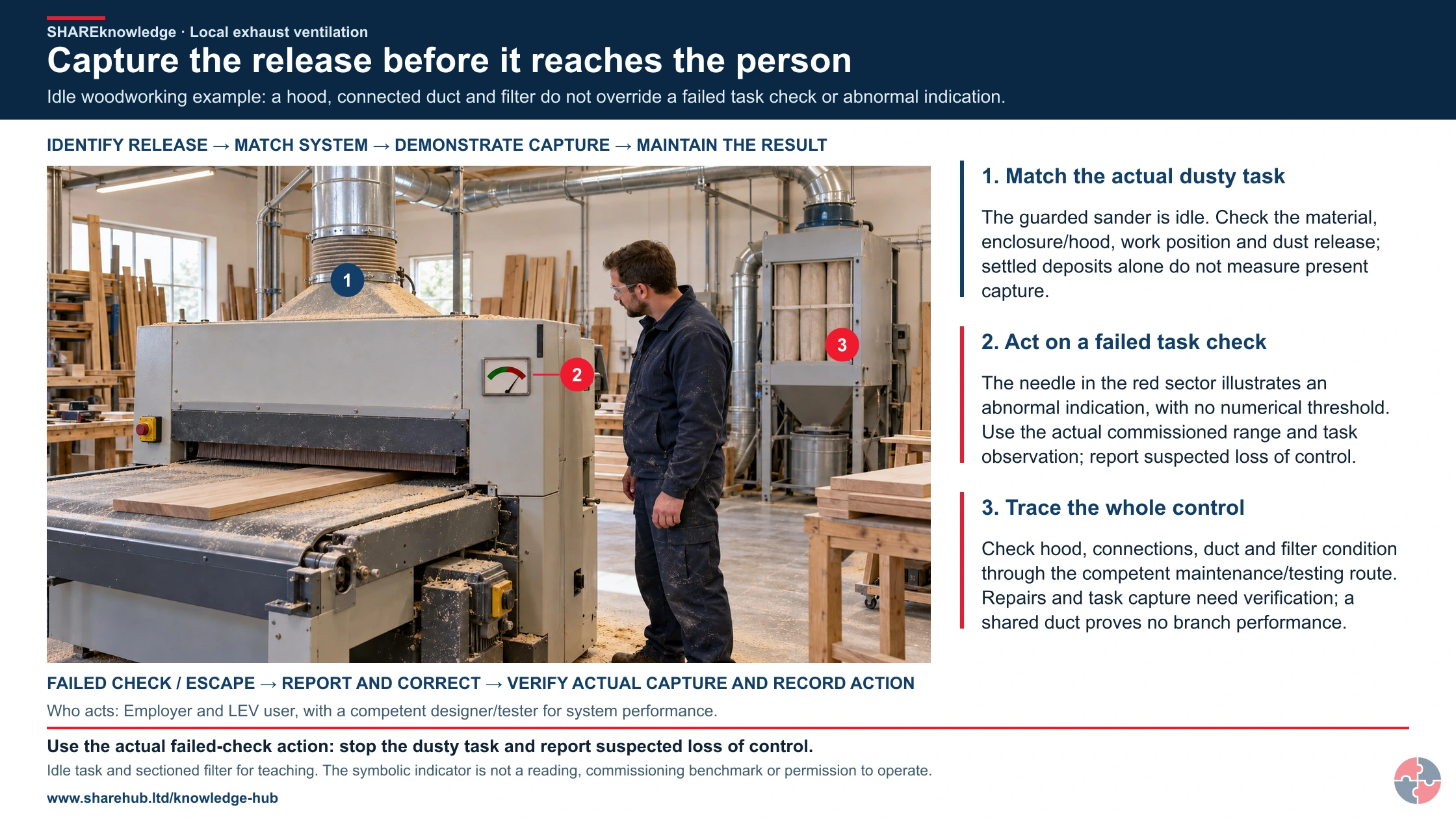
A realistic idle woodworking scene places the guarded sander and timber, dust deposits, connected hood/duct, symbolic abnormal indicator, filter cabinet and worker in one view. The worker remains clear of the feed opening and looks at the indicator; there is no active sanding, cleaning or repair. The red/green indicator with needle is deliberately unnumbered and illustrates a condition requiring the actual failed-check response; it is not a measured reading or a universal performance range. The exposed filter is an educational section. Three native markers connect the real release/task and hood, the indicator/task check, and the full duct/filter maintenance route. The complete native sequence follows identifying the release, matching the system, demonstrating capture and maintaining the result; a failed check or escape returns to reporting/correction and actual capture verification. Dust deposits are not proof of current airborne exposure or a specific fault, and visible connected ducting does not verify branch balance, compatible filtration, protection from fire/explosion, safe waste handling or discharge. All original written checks, failed-capture actions, commissioning benchmarks, testing/records, safeguards and source jurisdictions are retained. No airflow or pressure number, cleaning/filter-changing method, commissioning value or operating permission is introduced.
Idle woodworking example: a hood, connected duct and filter do not override a failed task check or abnormal indication.
- Identify the release. Locate the contaminant source, operator and nearby people during the actual task.
- Match the system. Confirm the hood, airflow path, process and work position suit one another.
- Demonstrate capture. Check performance at the release point; fan noise is not proof of capture.
- Maintain the result. Use pre-use checks, defect reporting and competent testing with records and action.
When the evidence does not fit: Poor capture, damaged equipment or an abnormal indicator requires correction and assessment of whether the affected task must be held.
Who acts: Employer and LEV user, with a competent designer/tester for system performance.
Changed workplace
Welding or fabrication: Keep the source inside the effective capture zone without pulling contamination past the face.
Woodworking: Match extraction to the machine and task; shared ducting alone does not prove each branch works.
Evidence check: A current test label does not override a failed task check or a moved hood.
Primary references: HSE: LEV commissioning and intended-performance benchmarks (GB) · HSE: LEV indicators, competence, testing and on-tool checks (GB) · HSE HSG258: controlling airborne contaminants (GB)
Open the complete HD image (new tab)Download image
Primary references: HSE: LEV commissioning and intended-performance benchmarks (GB) · HSE: LEV indicators, competence, testing and on-tool checks (GB) · HSE HSG258: controlling airborne contaminants (GB)
Operators and supervisors are often the first line of defence. They should know how the LEV should sound, look and perform. A green test label is useful, but it is not enough if the hood is damaged, the gauge reads outside the expected range, the hose is split, the filter alarm is active or dust is escaping.
Routine checks should be specific and repeatable. The best checklist asks closed questions that produce usable data: is the airflow indicator in range, is the hood in the right position, is the duct damaged, is the filter alarm clear, is the booth door closed, is the clearance time displayed, and has the worker been observed using it correctly?
Use the indicator and hood position as a pre-use check, and compare the task with the commissioned method. HSE LEV FAQ says an airflow indicator can immediately alert users to a problem; the indicator does not replace observation of capture. A broken hose, blocked filter, alarm or visible escape means stop the dusty task and report the defect.
| Check | What to look for | Action if failed |
|---|---|---|
| Hood position | Correct distance, angle and no obstruction. | Stop/reposition before starting task. |
| Airflow indicator | Gauge/manometer/tell-tale in expected range. Use an appropriate indicator with a range established during commissioning. A paper or plastic tell-tale is suitable only in very simple systems extracting low-hazard substances; it cannot be assumed suitable for other LEV. | Report and do not rely on system until checked. |
| Visible dust/fume/mist escape | Cloud moving away from hood or into breathing zone. | Stop and review capture, draughts and method. |
| Duct/hose condition | No split, crush, loose connection or blockage. | Replace/repair before use. |
| Filter condition/alarm | No blocked filter alarm or overloaded collector. | Change filter or call maintenance. |
| Booth/room condition | Doors, seals, filters, lights and pressure indicators normal. | Do not spray if booth condition is doubtful. |
| Correct work method | Worker not between source and hood; BA kept on when required. | Rebrief and supervise. |
What maintenance is needed to keep LEV effective?
LEV maintenance should be planned around wear, filter loading, contamination, process severity and statutory duties.
LEV performance deteriorates. Filters block, dust cakes, ducts corrode, flexible hoses split, fan belts slip, bearings wear, dampers are moved, seals fail, doors do not close, gauges drift and extraction arms are damaged. Maintenance is the control that prevents a good design from becoming a quiet failure.
Maintenance should also consider the hazard inside the LEV. Cleaning a collector full of toxic dust, changing contaminated filters, entering ductwork, scraping paint residues or maintaining solvent extraction can expose maintenance workers. Some tasks may need permits, method statements, isolation, RPE, disposal controls and decontamination.
| Maintenance area | What should be managed | Evidence |
|---|---|---|
| Filters and collectors | Loading, replacement, cleaning method, waste route and differential pressure. | Filter change record and waste/disposal evidence. |
| Hoods and enclosures | Damage, seal condition, doors, side panels, booth structure and access openings. | Inspection record and defect close-out. |
| Ductwork and hoses | Leaks, corrosion, wear, loose joints, blockages and crushed flexible duct. | Inspection and repair log. |
| Fan and drive | Fan rotation, belts, bearings, vibration, noise, speed and duty. | Maintenance record and test data. |
| Indicators and alarms | Calibration, visibility, expected range and user understanding. | Gauge/alarm check record. |
| Spray booth filters | Intake/extract filter condition, pressure balance and overspray loading. | Booth maintenance log and filter schedule. |
| Contaminated maintenance | Exposure during filter changes, duct cleaning and collector emptying. | Permit/method statement, PPE/RPE and disposal records. |
What is LEV thorough examination and test?
Most LEV must be thoroughly examined and tested at least every 14 months; specified processes need shorter legal intervals.
HSE LEV FAQ explains the 14-month maximum, the five-year minimum for TExT reports and keeping installed-system information for the equipment life. GB COSHH Schedule 4 specifies shorter maximum intervals for listed processes. HSENI LEV guidance states the NI examination requirement. A competent person should set a shorter planned interval where deterioration can defeat control before the legal maximum.
The examiner needs the commissioning standard, current process, user manual/logbook, maintenance history, previous reports and any exposure evidence. A sticker or pass based only on airflow is not a demonstration that the actual contaminant is captured. Critical defects require immediate action and a documented decision about continued use.
| Check | Decision and record | Failure action | Direct source |
|---|---|---|---|
| Due date | Most systems: no more than 14 months; review Schedule 4 and deterioration risk. | Stop relying on an overdue or unverified control until competent assessment. | HSE examination FAQ |
| Real capture | Observe representative work and compare with commissioning performance. | Restrict process and repair/adjust if contaminant escapes. | HSG258 |
| Record | Keep the TExT report at least five years and installed-system information for its life. | Recover records and establish a defensible benchmark. | HSE record guidance |
What should an LEV examination look at?
Testing should examine both hardware performance and real control effectiveness.
Airflow numbers matter, but they are not the whole story. A hood can have an impressive face velocity while the worker still breathes contaminant because the hood is mispositioned, the task changed or the cloud has too much momentum. Conversely, a system may need exposure monitoring to show adequate control where the hazard is serious or the contaminant is invisible.
The examiner should be given the commissioning report, user manual, logbook, previous TExT report, maintenance records, process changes and any exposure monitoring data. Without those, the examination becomes detective work and may not be able to judge performance against intended design.
HSG258 recommends checking the whole control chain. Compare pressure/flow with the commissioning values, inspect ducts and filters, and use a suitable qualitative capture or containment check during representative work. Where a serious or invisible hazard leaves uncertainty, a competent occupational hygienist can design personal exposure monitoring.
| Test element | Purpose | Good output |
|---|---|---|
| Visual examination | Find damage, leaks, corrosion, poor connections and misuse. | Clear defects with photographs or location references. |
| Airflow/pressure measurements | Check system performance against benchmarks. | Measurements at defined test points with comparison. |
| Capture/containment test | Confirm contaminant is controlled at the task. | Smoke, dust lamp, tracer or process observation evidence. |
| Filter/air cleaner review | Check loading, bypass, leaks and suitability. | Pressure readings and maintenance actions. |
| Discharge review | Check extracted air reaches a safe place. | Discharge location and re-entry risk review. |
| Operator use | Check whether real work matches design assumptions. | Observation and corrective training if needed. |
| Report and label | Communicate pass/fail, defects and next due date. | Clear hood labels and action requirements. |
Why do clearance times matter?
Clearance time is the period needed for a booth, room or enclosure to remove airborne contaminant after the process stops.
Clearance time is especially important in spray booths and spray rooms because isocyanate paint mist can be invisible. A sprayer may feel the job is finished when the gun stops, but the breathing hazard can remain in the air. HSE guidance is clear that the booth or room takes time to clear and that people need to know that time.
The clearance time should be measured, rounded up sensibly, displayed on the booth or room entrance and communicated to anyone who uses or enters the area. Workers using air-fed BA must keep it on until they have left the spraying area or the area is clear. Clearance time should be retested when filters are near change, after system changes, after airflow concerns and as part of examination/testing arrangements.
HSE bodyshop clearance-time guidance requires a measured and clearly displayed time. Keep air-fed breathing apparatus on while in the spray area until clearance is achieved; do not infer a safe time from when the gun stopped.
| Control | What good looks like | Failure to avoid |
|---|---|---|
| Measurement | Use a suitable smoke/fog method to fill the empty booth/room and time how long ventilation takes to clear visible mist. | Guessing from manufacturer claims or old habits. |
| Worst-case timing | Measure under conditions that represent poor-case clearance, such as before filter changes where relevant. | Testing immediately after new filters and assuming it always applies. |
| Display | Post the clearance time clearly at the booth or room entrance. | Clearance time hidden in a folder. |
| Training | Sprayers, inspectors, cleaners and supervisors know they must wait or keep BA on. | People entering to inspect finish while mist remains. |
| Re-test triggers | Retest after filter changes, airflow changes, booth modifications or poor monitoring results. | Continuing after visible mist, leakage or pressure concerns. |
| Interlocks/sensors | Use interlocks or warning systems where appropriate to prevent early entry or visor removal. | Relying only on memory in busy bodyshop conditions. |
How should LEV apply to accident repair spray booths?
An accident repair spray booth is a high-value LEV example because control depends on booth performance, work practice, air-fed BA and health surveillance together.
In a motor vehicle accident repair centre, spray painting often involves 2-pack isocyanate paints. Spraying produces fine aerosol mist and may use large amounts of product in a short time. The booth or room is therefore not just a workspace; it is an exposure-control enclosure. It must control overspray, prevent mist leakage, supply suitable airflow, filter or discharge extracted air safely, support bake cycles where used and give a known clearance time.
The operational control layer is the routine discipline around the booth. A bodyshop should know who may spray, which products are authorised, whether the booth is within examination date, what the pressure/gauge readings mean, whether filters are loaded, whether the air-fed BA is working, whether biological monitoring is in place, whether health surveillance is current and whether anyone has reported chest tightness, wheeze or night-time symptoms.
| Control layer | What it should achieve | Evidence |
|---|---|---|
| Product control | Identify 2K/isocyanate paints, primers, lacquers and cleaners. | SDS, product register and COSHH assessment. |
| Booth engineering | Control mist, overspray and airflow through downdraught/crossflow design. | Commissioning data, TExT report and maintenance log. |
| Clearance time | Prevent early entry or visor removal while mist remains. | Smoke-test result displayed at entrance. |
| Air-fed BA | Protect sprayers while mist is present. | BA checks, air quality tests, low-flow warning and training. |
| Work practice | No spraying outside the booth, no visor lifting, no uncontrolled gun cleaning. | Supervisor observations and worker briefings. |
| Biological monitoring | Check whether real exposure is occurring despite controls. | Monitoring programme and action review. |
| Health surveillance | Detect early asthma or dermatitis signs. | Occupational health scheme and confidential records. |
| Maintenance | Keep filters, doors, seals, gauges, fans and booth balance effective. | Filter schedule, defect log and repairs. |
What does a strong accident repair centre example look like?
A worked example helps learners see how LEV connects COSHH, RPE, occupational health and daily supervision.
A busy accident repair centre repairs a side impact on a car. The team strips, fills and sands body panels, cleans surfaces, masks the vehicle, mixes a 2K product, sprays primer and topcoat in the booth, uses bake mode, cleans the gun and then polishes the finish. There are multiple airborne hazards: filler dust during sanding, solvent vapour during cleaning, isocyanate mist during spraying, and contaminated surfaces during clean-up.
The centre's controls should not start and end with a booth certificate. The sander needs effective on-tool extraction; the booth needs current TExT, functioning filters and displayed clearance time; the sprayer needs air-fed BA and training; the supervisor needs to stop spraying outside the booth; biological monitoring checks whether exposure is really controlled; and health surveillance identifies possible occupational asthma or dermatitis early, prompting clinical assessment and action to prevent further harmful exposure. Symptoms may already reflect sensitisation; surveillance cannot guarantee detection before sensitisation or replace exposure prevention.
| Task stage | LEV or ventilation control | Diploma-level learning point |
|---|---|---|
| Body filler sanding | Use on-tool extraction matched to the sander and dust extractor. | Dust control starts before the paint booth stage. |
| Surface cleaning | Use controlled ventilation and avoid solvent vapour build-up. | Vapour control may involve COSHH and DSEAR thinking. |
| Mixing 2K paint | Use controlled area, lids, small quantities and ventilation. | LEV may not control all skin/splash risks; COSHH must cover routes. |
| Spraying | Use the booth/room with air-fed BA, no bystanders and no visor lifting. | The booth and BA operate as a combined barrier system. |
| Bake/curing | Maintain booth airflow/balance and prevent leakage during operating modes. | Filter loading or failed pressure sensors can reverse the expected control. |
| Clearance period | Wait for displayed clearance time or keep BA on until clear/outside. | The hazard may be invisible after the trigger is released. |
| Gun cleaning | Control aerosol/vapour and avoid spraying cleaner without protection. | Post-spray tasks can create exposure if not assessed. |
| Monitoring review | Use biological monitoring and symptom reports to test real exposure control. | Health evidence can reveal failures that airflow readings miss. |
How should LEV and RPE work together?
RPE may be needed where LEV cannot provide adequate control alone, but it must be managed as a programme.
RPE is often needed for high-risk spray work, maintenance, filter changes, breakdowns, short-duration residual exposure or unusual tasks. In isocyanate spray booths, HSE guidance emphasises air-fed breathing apparatus because filtering respirators are not suitable for spraying 2K isocyanate paints.
The interface is important. If LEV is weak, RPE may carry too much of the risk. If RPE is weak, the worker may be exposed even though the booth is running. Air supply quantity, quality, low-flow warnings, visor visibility, compressor location, hose condition, user checks and training all matter.
| Issue | Good control | Weak control |
|---|---|---|
| Spray painting | Air-fed BA worn while mist is present and until clear/outside. | Half-mask filtering respirator used for 2K spraying. |
| RPE selection | assigned protection factor (APF), contaminant, task duration and wearer considered. | Generic mask selected from stores. |
| Air quality | Breathing air tested and maintained to suitable standard/frequency. | Compressor air assumed clean. |
| Fit testing | Tight-fitting RPE face fit tested where relevant. | Beards, poor fit or no fit test. |
| Maintenance tasks | RPE used for contaminated filter/duct work where needed. | Maintenance worker opens collector with no exposure controls. |
| Behaviour | Users know when not to lift visor or remove RPE. | Worker checks finish while still surrounded by mist. |
When is exposure monitoring needed?
Monitoring checks whether controls are actually preventing exposure, especially where the hazard is serious or invisible.
LEV measurements show how the system performs, but exposure monitoring shows what reaches people. For substances with WELs, monitoring may help assess whether control is adequate. For isocyanate spray work, biological monitoring is especially valuable because the sprayer's exposure depends on both booth performance and behaviour.
Monitoring should be planned by competent people. It should answer a clear question: is exposure controlled during this task, in this booth, with these work practices, using this RPE, under these real conditions?
| Monitoring type | What it tells you | Use case |
|---|---|---|
| LEV airflow/pressure checks | Whether the system is within expected operating range. | Routine user and maintenance checks. |
| Smoke/dust lamp test | Whether contaminant is captured or leaks. | Hood performance, booth clearance and training. |
| Personal air monitoring | Worker exposure during task. | WEL comparison and COSHH review. |
| Static or area monitoring | Workplace contaminant levels away from source. | Bystander exposure or leakage concerns. |
| Biological monitoring | Whether substance has entered the body. | Isocyanate spray work and other specific substances. |
| Health surveillance signal | Whether symptoms suggest inadequate control. | Asthma, dermatitis or respiratory sensitisation programmes. |
How does health surveillance connect to LEV?
The assessment must establish the applicable health-surveillance criteria: a relevant identifiable disease or adverse effect, sufficient likelihood under the work conditions and a valid, safe detection method, with competent scheme design and a response plan.
LEV should reduce exposure, but it does not remove the need to think about health surveillance. If the substance can cause asthma, dermatitis, cancer or other occupational disease and the risk remains, workers may need appropriate surveillance.
For accident repair spray work, respiratory health surveillance and biological monitoring are important because isocyanates can cause occupational asthma and because real exposure can occur when people lift visors, enter early, clean guns poorly or work in a leaking booth.
| Health risk | LEV relevance | Surveillance/response |
|---|---|---|
| Occupational asthma | LEV and RPE must control inhaled sensitisers. | Respiratory questionnaire, lung function and prompt OH referral. |
| Dermatitis | LEV may not control skin contact. | Skin checks, glove review and hygiene controls. |
| Cancer risks | LEV reduces carcinogen exposure but long-term prevention matters. | Exposure records and specialist surveillance where required. |
| Metal fume effects | LEV captures welding/metal fume but performance can drift. | Symptom reporting and exposure review. |
| Isocyanate exposure | Booth and BA controls can fail silently. | Biological monitoring and health surveillance. |
Use the statutory/risk-based criteria rather than offering a generic screening test for every carcinogen. Biological monitoring checks uptake/exposure control; health surveillance checks for relevant health effects and needs an agreed clinical response. Sources: HSE health-surveillance criteria; HSE motor-vehicle health surveillance; HSE clearance-time measurement.
How do DSEAR and fire risk affect LEV?
LEV can control flammable vapours, mists and dusts, but it can also create fire or explosion issues if badly designed.
A ventilation system extracting solvent vapour, paint mist, combustible dust or flammable gases may need DSEAR review. The question is not only whether LEV reduces inhalation exposure, but whether the hood, duct, fan, filter, discharge and cleaning method could collect an ignitable mixture or combustible deposit.
For spray booths, solvent vapour, paint overspray, filters, static electricity, hot surfaces, electrical equipment, bake cycles and waste handling may all need fire and explosion controls. LEV should therefore link to hazardous area assessment, ignition control, housekeeping, filter change and emergency arrangements where relevant.
For GB, DSEAR 2002 and HSE DSEAR guidance require fire/explosion risk assessment and control where dangerous substances are present. In Northern Ireland, use DSEAR (NI) 2003 and HSENI explosive-atmosphere guidance. A combustible-dust or solvent LEV design needs both COSHH exposure control and a separate ignition/accumulation decision; a health-control airflow number alone is insufficient.
| Issue | Why it matters | Control focus |
|---|---|---|
| Solvent vapour | Can form flammable atmosphere. | Ventilation, zoning, ignition control and safe discharge. |
| Combustible dust | Can accumulate in ducts/filters and ignite. | Transport velocity, cleaning, explosion protection where needed. |
| Paint filters | Overspray residues may create fire load. | Filter change, waste storage and housekeeping. |
| Static electricity | Airflow and mists can create ignition concerns. | Bonding/earthing and suitable equipment where needed. |
| Fan/electrical equipment | May be ignition source if unsuitable. | DSEAR assessment and suitable equipment selection. |
| Recirculation | Vapours should not be recirculated inappropriately. | Safe discharge and environmental review. |
What happens when a new workpiece changes the capture conditions?
A normal indicator reading describes one measured condition, not every possible use of the system. A changed workpiece, emission direction, operator position or simultaneous hood use can defeat capture even where the fan runs and a familiar gauge remains in range. Screen changes before using the new process as routine work. Related guidance: Commission your LEV system.
In an illustrative fabrication workshop, a bench extraction hood was commissioned for a small component held inside its defined working zone. A larger component requires the operator to stand between the emission and hood and rotate the piece during finishing. The supervisor holds the changed operation. The old commissioning report remains valuable evidence of the previous configuration, but it does not establish control of the new one. Related guidance: Commission your LEV system.
The process owner and competent LEV specialist establish the substances, emissions, work rate, operator movements and simultaneous demands. They consider source reduction and improved enclosure or task layout before treating greater fan output as the answer. Any change to ducts, fan, filtration or discharge needs assessment of system balance, contaminant compatibility and fire/explosion or re-entry consequences where relevant. Related guidance: Commission your LEV system.
The acceptance test represents the intended operation and relevant adverse conditions. It observes capture or containment and compares defined technical measurements with the appropriate design and commissioning benchmarks. Where the hazard or uncertainty calls for it, competent exposure assessment supports the decision. A visually clear room or one airflow number cannot alone establish adequate control of an invisible harmful contaminant. Related guidance: Commission your LEV system.
Before release, provide a comprehensible record of the authorised process/configuration, hood use, indicators and action limits, restrictions, maintenance and user instruction. The operator demonstrates the new working zone and a stop when the arrangement cannot be maintained. Update the schematic, manual, logbook and future examination basis; retain the earlier configuration history so later changes can be traced. Related guidance: Commission your LEV system.
Guidance for these decisions: Commission your LEV system; HSG258 controlling airborne contaminants; LEV frequently asked questions. Apply the legal route for the work location; illustrative scenarios are SHARE teaching examples.
Where do LEV systems commonly fail?
LEV failures are usually predictable and often visible if people know what to look for.
Many failures are not dramatic. The system still makes noise, so everyone assumes it is working. Meanwhile, the hood is moved, the filter blocks, the airflow indicator is ignored, the capture zone is too small, the duct leaks, the process changes or the worker's breathing zone sits directly in the contaminant path.
A high-quality LEV review should help learners challenge that false sense of security. The question is not 'is the fan on?' The question is 'is the contaminant being captured or contained under the real conditions of work, and is the evidence strong enough to prove it?'
| Failure route | How harm can result | Control response |
|---|---|---|
| Hood too far from source | Contaminant escapes into breathing zone. | Move hood, redesign enclosure or change work method. |
| Worker between source and hood | The airflow pulls contaminant across the worker's face before it reaches the hood. | Reposition the task, hood or worker and retrain the method. |
| Blocked filter | Airflow drops, booth pressure changes or contaminant bypasses the intended route. | Use pressure checks, filter alarms, change schedules and defect escalation. |
| Damaged duct | Leaks, crushed hoses or loose joints reduce capture and may release contaminant elsewhere. | Inspect, repair and retest affected sections before normal use. |
| Poor make-up air | Room pressure or draught patterns undermine capture, comfort and booth performance. | Review replacement air, door discipline, room balance and ventilation interaction. |
| Fan belt failure or fan wear | The system may be noisy but no longer moves enough air. | Include fan, belt, bearing, speed and vibration checks in planned maintenance. |
| No airflow indicator | Users cannot tell whether the LEV is within the expected range before use. | Fit suitable indicators or gauges and train users on the normal range. |
| No commissioning data | TExT cannot compare against intended performance. | Commission/recommission and set benchmarks. |
| User does not understand gauge | Failure is visible but ignored. | Train users on normal range and escalation. |
| Process changes | LEV no longer matches the emission. | Management of change and reassessment. |
| Clearance time ignored | People enter a booth or remove BA while invisible mist may still be present. | Measure, display, train, supervise and investigate any early-entry behaviour. |
| TExT defects not closed | Known control weaknesses remain in service until exposure becomes normalised. | Use an action tracker, priority grading, owner, due date and verification evidence. |
| Maintenance exposes workers | Filter/duct cleaning creates concentrated exposure. | Permit, method statement, RPE and waste controls. |
What evidence shows LEV is managed properly?
Evidence should prove that the LEV was specified, installed, used, maintained, examined and reviewed against the real hazard.
Good evidence is not just a TExT certificate. It includes the COSHH assessment, design specification, commissioning report, user manual, logbook, daily checks, maintenance records, repair close-out, TExT reports, exposure monitoring, health surveillance triggers, training records, DSEAR review where relevant and management review of defects.
For accident repair, the evidence should also show booth clearance time, BA checks, breathing-air quality tests, biological monitoring, respiratory health surveillance, spray booth maintenance, filter changes and supervisor observations.
| Evidence | Why it matters | Quality check |
|---|---|---|
| COSHH assessment | Shows why LEV is required and what it controls. | Does it describe the actual task and contaminant? |
| Specification | Tells supplier what must be controlled. | Does it include worker position, process and proof criteria? |
| Commissioning report | Creates performance benchmark. | Is it available and linked to test points? |
| User manual/logbook | Shows intended use, checks and maintenance. | Are checks recorded and defects closed? |
| TExT report | Statutory performance review. | Does it compare with intended performance and state defects clearly? |
| Exposure monitoring | Checks worker exposure where needed. | Are results interpreted and acted on? |
| Training records | Shows users understand correct use and failure signs. | Does training include practical demonstration? |
| Spray booth records | Shows clearance, BA and booth condition. | Are clearance time and biological monitoring reviewed? |
How can control be restored when the commissioning baseline is missing?
Separate two questions: whether exposure is adequately controlled now, and whether the evidence needed to maintain and examine the system is available. Replacing a missing sticker or copying a neighbouring machine’s report resolves neither question. A competent assessment must identify the actual system and what it is intended to control. Related guidance: Commission your LEV system.
First recover available design records, manuals, drawings, hood identities, process conditions, maintenance and examination history. Record which evidence is absent or unreliable. Give the examiner access to representative work and the people who use the system. A number without its measurement point, method, operating state and comparison basis cannot serve as a defensible performance benchmark. Related guidance: Commission your LEV system.
Where the baseline cannot be recovered, competent commissioning or recommissioning work should establish adequate control and appropriate benchmarks. Agree any interim restrictions from the actual hazard and evidence; the page gives no blanket permission to continue while paperwork is recreated. Temporary protection must itself be assessed and cannot be treated as equivalent to a failed engineering control without evidence. Related guidance: Commission your LEV system.
Recovery finishes with a tested control, usable user information, a maintenance and examination basis, and an owner who verifies those items are in use. A report marked satisfactory with unresolved capture, system-identity or compatibility questions should be challenged. Review an examination interval against the applicable legal maximum, specified-process exceptions and deterioration risk; the maximum is not a guarantee of continued effectiveness. Related guidance: Commission your LEV system.
Guidance for these decisions: Commission your LEV system; LEV frequently asked questions; HSG258 controlling airborne contaminants. Apply the legal route for the work location; illustrative scenarios are SHARE teaching examples.
What should managers check to assure LEV is really working?
Managers do not need to be LEV examiners, but they do need to ask enough good questions to know whether the control is alive.
The manager assurance role is to connect the technical evidence with daily reality. A TExT report may say a system passed, but if operators do not know the airflow indicator range, if defects stay open, if filter changes are missed, if exposure monitoring trends upward or if health surveillance raises concerns, the control system is not healthy.
This checklist is deliberately practical. It can be used during a workshop walk-round, bodyshop review, COSHH review, audit, management meeting or investigation after exposure concern.
| Assurance question | Good evidence | Action if weak |
|---|---|---|
| Is the LEV matched to the process? | COSHH assessment, specification and commissioning report describe the actual task, contaminant and worker position. | Reassess the task and involve competent LEV/COSHH support. |
| Are users trained? | Workers can explain what the LEV controls, normal indicator range, correct hood position and stop-work triggers. | Refresh practical training and supervisor observation. |
| Are indicators understood? | Gauges or indicators are visible, labelled with expected range and checked before use. | Improve labelling, training and first-line checklist. |
| Are defects acted on? | Defects have owners, due dates, priority and close-out evidence. | Escalate overdue defects and restrict use where control is doubtful. |
| Are TExT records current? | Reports are in date, compare with commissioning data and include clear actions. | Arrange competent TExT and review whether interim controls are needed. |
| Are maintenance tasks completed? | Filter changes, fan/belt checks, duct inspections and contaminated-maintenance controls are recorded. | Review maintenance frequency, competence and spare-part control. |
| Are exposure or health results suggesting failure? | Exposure monitoring, biological monitoring and health surveillance are reviewed together. | Investigate LEV, RPE, work method, supervision and product substitution. |
| Is spray booth clearance controlled? | Clearance time is measured, displayed, trained and observed in practice. | Retest clearance time, brief users and investigate early entry or visor lifting. |
What should the risk or assurance register include for LEV?
A risk register should make LEV controls visible and owned, especially for high-risk substances.
A risk register should help people make decisions. The fields below are useful because they connect each risk scenario to ownership, assurance and review triggers instead of leaving the register as a static list.
| Register field | Why it matters | Example |
|---|---|---|
| Substance/process | Identifies what the LEV controls. | 2K paint spraying, wood machining, welding fume. |
| Health outcome | Shows why the control is safety-critical. | Occupational asthma, cancer, COPD, dermatitis. |
| LEV asset ID | Connects risk to equipment. | Spray booth SB-01 or extractor EXT-04. |
| Performance benchmark | Defines expected airflow/pressure/control. | Commissioning data and hood label. |
| Inspection frequency | Defines daily/weekly/monthly/TExT checks. | Daily user check, weekly supervisor check, 14-month TExT. |
| Critical defects | Triggers stop-work or temporary controls. | Failed airflow, filter alarm, no clearance time. |
| Monitoring evidence | Shows control effectiveness. | Air monitoring, biological monitoring, health surveillance trend. |
| Action owner | Makes repairs and improvements accountable. | Workshop manager, facilities lead, HSE adviser. |
Which UK legal duties apply to LEV?
Apply the legal route for the work location and test the actual controls, responsibilities and records.
Great Britain and Northern Ireland have distinct primary and management regulations. Official guidance helps interpret practical arrangements, but is not a replacement for the applicable instrument. Specialist legal advice is needed for a disputed duty or enforcement decision.
| Jurisdiction | Direct instrument or guidance | Operational decision supported |
|---|---|---|
| Great Britain | Health and Safety at Work etc. Act 1974 | General employer, worker and public protection duties. |
| Northern Ireland | Health and Safety at Work (NI) Order 1978 | The separate NI general-duty route. |
| Great Britain | Management of Health and Safety at Work Regulations 1999 | Risk assessment, arrangements, competence and emergency planning. |
| Northern Ireland | Management of Health and Safety at Work Regulations (NI) 2000 | The separate NI management and risk-assessment route. |
| Great Britain | COSHH Regulations 2002 | Prevention/control, maintenance and TExT; Schedule 4 process intervals. |
| Northern Ireland | COSHH Regulations (NI) 2003 | Separate NI exposure-control and examination route. |
| Northern Ireland | HSENI LEV guidance | NI practical examination and competence advice. |
| Great Britain | DSEAR 2002 | Fire/explosion risk of solvent, paint mist and combustible-dust extraction. |
| Northern Ireland | DSEAR (NI) 2003 | Separate NI fire/explosion route for dangerous-substance extraction. |
How could BuildOut Ltd manage this in practice?

BuildOut Ltd would specify and verify local exhaust ventilation against the actual contaminant-producing task, then keep users able to recognise loss of control.
BuildOut Ltd · practical example
Accept extraction against the process it must control
The key lesson An extractor being switched on is not proof that harmful material is captured before it reaches people's breathing zones.
The situation: A subcontractor proposes a sanding station for joinery work during fit-out. An extraction unit is available, but nobody can yet show that its hood and airflow suit the dust source and working position.
Why this matters: Hood position, tool connection, make-up air, blocked filters and the user's position can all change performance.
How BuildOut Ltd would manage it
- Specify the duty — Project Manager. Describe the material, process, contaminant and normal working positions to a competent LEV supplier or specialist. Agree the required control performance rather than buying on motor power alone.
- Verify the installation — Plant and Procurement Coordinator. Obtain competent commissioning evidence for the arrangement and its actual operating conditions. Resolve limitations before accepting the station as the control for routine work.
- Teach the usable checks — Trade Supervisor. Show users the correct hood or tool connection, indicators and checks set by the system instructions. Explain what a failed check means and who can correct it.
- Maintain the benchmark — Site Manager. Keep the user manual, logbook, maintenance and required examination arrangements connected to the identified system. Do not treat routine user checks as a replacement for competent examination.
- Review changed work — Health and Safety Manager. Reassess a moved hood, additional tool, new material or altered process. Use the commissioning benchmark and competent advice to confirm the revised system still controls exposure.
When the conditions change
- Recognise the trigger
- The indicator fails, capture is visibly poor or the process changes.
- Make the immediate decision
- Do not continue the affected dust-producing task using unverified extraction.
- Verify the next step
- The Site Manager checks restored capture performance against the commissioning benchmark, the correct hood or connection and usable system indicators before restarting sanding.
What good looks like
Users can identify their system, demonstrate its intended setup and explain a stop condition. Managers can connect its performance evidence to the task being carried out.
Evidence to look for: Process specification, commissioning report, operating instructions, user checks, maintenance and examination records.
Common mistake to avoid: Relying on noise from the fan as evidence that the extraction is working.
Apply this to your work: What shows that your extraction captures the contaminant at source under normal working conditions?
Guidance behind the management approach: HSE: commissioning local exhaust ventilation. Use the topic's legal and technical guidance for the applicable work and location.
BuildOut Ltd is a contractor with workshops, cutting rooms, woodworking, welding, plant maintenance and subcontracted accident repair activity. It treats LEV as an occupational-health barrier that must be specified, tested, maintained and verified rather than simply bought and forgotten.
| Management element | How the business would manage it | Evidence to review |
|---|---|---|
| Assessing | BuildOut identifies dust, fume, mist and vapour tasks and links each LEV asset to a COSHH assessment and health risk. | COSHH register, LEV asset register and health-risk map. |
| Specifying | LEV purchases require task description, contaminant type, worker position, capture requirement and commissioning evidence. | LEV procurement specification and acceptance test. |
| Implementing | Operators use hoods, on-tool extraction, booths and gauges correctly, with stop-work triggers for failed capture. | User instructions and supervisor observations. |
| Maintaining | Filters, ducts, fans, hoods, pressure gauges and booths are checked and repaired through planned maintenance. | Logbook, maintenance schedule and defect tracker. |
| Verifying | TExT, exposure monitoring, biological monitoring and health surveillance data are reviewed together. | Assurance dashboard and management review. |
| Learning | Any asthma symptom, high biological result, failed TExT or visible dust escape triggers investigation and control review. | Incident/RCA record and improved standards. |
How does this topic align with ISO 45001?
Use these examples to connect the relevant clauses to your own occupational health and safety management system. For each clause, identify the person responsible, the control in use and the evidence that it works.
Scroll across the table to read all four columns.
| ISO 45001 clause | How it applies | What to put in place | How to verify it works |
|---|---|---|---|
| 8.1.1 Operational planning and control | Local exhaust ventilation (LEV) is an operating control for capturing harmful dust or fume where it is produced. BuildOut needs the sanding station to work in the positions and tasks that joiners actually use. | Agree with the subcontractor how operators position the hood and workpiece and check the LEV before sanding. Commission it for the intended work and define when to stop and report a problem. | The commissioning record shows that the LEV captures dust at the actual work positions. An operator demonstrates the setup and the response to a failed check. |
| 8.1.3 Management of change | Changing the sanding tool, hood position or work layout can change capture performance. | Require the supervisor to review those changes with the LEV supplier or a competent adviser before affected work resumes. Update the work instruction and brief operators on any new setup. | A change record shows the new configuration, the verification of capture in use and the decision to release it for use. |
| 9.1.1 Monitoring and evaluating performance | Commissioning gives BuildOut a baseline for judging whether the system continues to control dust in service. | Set up operator checks, planned maintenance and competent examination against the commissioning information. Give supervisors a route to act on falling performance or visible escape. | Keep performance results against the commissioning baseline, with repair and recheck records for defects. Site observations confirm workers can position the hood and still do the job. |
Selected applications of ISO 45001:2018 with Amendment 1:2024. Use the current standard for a full assessment and check the legal duties that apply to the work and location.
ISO 45001:2018 · 2024 climate action amendment · ISO 45002 implementation guidance · ISO technical committee clause FAQ
How should LEV competence be demonstrated at each role?
Assess the real process and assigned role. Basic user instruction covers the working zone and indicator; specifying or examining the system requires additional technical competence. A course certificate alone cannot demonstrate that a person can interpret this system’s control evidence. Related guidance: Commission your LEV system.
Use the larger-component scenario as a safe exercise. Ask the participant to identify the changed emission and working position, hold the operation within their role and state which evidence would permit recovery. Qualitative tests and measurements must use suitable safe methods chosen by a competent person; do not introduce an unassessed substance or release merely to make a demonstration visible. Related guidance: Commission your LEV system.
Record process/configuration, assessor competence, observation, limits and learning actions. Reassess when the contaminant, process, layout, control system, role or evidence changes. An assessment should test recognition of uncertainty as well as routine success. Related guidance: Commission your LEV system.
| Role and assessor | Observed decision | Limits and failure response | Record and reassessment |
|---|---|---|---|
| User — competent supervisor | Demonstrate working zone, correct hood position, indicator check and response to loss of capture. | Stop on failed indication, visible escape or changed task outside the authorised method. | Actual process/hood and observed stop response; reassess after task or instruction change. Related guidance: Commission your LEV system; HSG258 controlling airborne contaminants; LEV frequently asked questions. |
| Supervisor — competent process/LEV assessor | Observe representative work and challenge a normal gauge when the worker is in the contaminant path. | Hold changed work; do not set engineering performance limits without competence. | Observed configuration and escalation; reassess after failed control or new workpiece. Related guidance: Commission your LEV system; HSG258 controlling airborne contaminants; LEV frequently asked questions. |
| Maintainer — competent maintenance assessor | Explain isolation and contaminated-part handling; demonstrate the authorised replacement and hand-back checks. | Do not disturb contaminated filters/ducts or change fan settings outside the safe method. | Work scope, contamination controls and verified hand-back; reassess after component or method change. Related guidance: Commission your LEV system; HSG258 controlling airborne contaminants; LEV frequently asked questions. |
| Manager/procurement — competent process/safety reviewer | Specify the actual process and acceptance evidence and resource defective-control recovery. | A cheap hood or examination sticker cannot establish suitability. | Specification, restrictions and acceptance decision; review changed demand or repeat failure. Related guidance: Commission your LEV system; HSG258 controlling airborne contaminants; LEV frequently asked questions. |
| Designer/commissioner — competent technical reviewer | Define emissions, operating envelope, balance, capture/containment and meaningful benchmarks. | State untested conditions and compatibility limits; resolve material uncertainty before acceptance. | Signed technical evidence, methods/configuration and user handover; review changed system/process. Related guidance: Commission your LEV system; HSG258 controlling airborne contaminants; LEV frequently asked questions. |
| Examiner — competent examination reviewer | Compare whole-system performance with intended process and prior benchmark; explain defect significance. | Do not infer complete control from airflow alone or hide missing baseline. | Report, tests, comparison and clear required action; reassess new scope or uncertain interpretation. Related guidance: Commission your LEV system; HSG258 controlling airborne contaminants; LEV frequently asked questions. |
| Hygienist/health interface — qualified relevant specialist | Design/interpret exposure assessment and identify health-surveillance needs where required. | Exposure monitoring and health evidence do not replace effective engineering control. | Appropriate exposure/health records and necessary control advice; review changed hazard or findings. Related guidance: Commission your LEV system; HSG258 controlling airborne contaminants; LEV frequently asked questions. |
Guidance for these decisions: Commission your LEV system; HSG258 controlling airborne contaminants; LEV frequently asked questions. Apply the legal route for the work location; illustrative scenarios are SHARE teaching examples.
What training and competence levels support LEV control?
Training should match the role: user, supervisor, maintainer, manager, COSHH assessor, examiner or specialist.
The minimum standard is that users know why the LEV is there, how to use it, what normal performance looks like, what the airflow indicator means, what not to change and when to stop. Supervisors need enough understanding to observe work and challenge poor capture. Maintainers need safe methods for contaminated parts.
More advanced training should develop the ability to specify, commission, interpret TExT reports, review exposure monitoring, select RPE, assess spray booth clearance and integrate LEV into occupational health and assurance systems.
| Training level | Who needs it | What it should cover |
|---|---|---|
| General awareness | Everyone who may encounter the topic. | Plain-English awareness of LEV local exhaust ventilation, why it matters, common situations, basic controls, reporting routes and where to get help. |
| Topical practical training | Workers most directly involved in the task or support process. | Task examples, control expectations, warning signs, stop-work points, escalation and records. |
| Supervisor and manager training | People allocating work, authorising tasks, holding conversations or checking controls. | Decision quality, private conversations, supervision, risk assessment, evidence, escalation and review. |
| Specialist or competent-person training | Occupational hygienists, LEV designers, TExT examiners, ventilation engineers, COSHH specialists, spray booth engineers, RPE specialists and occupational health professionals where high-risk airborne contaminants are controlled. | Technical assessment, occupational health, fire safety, process safety, auditing, investigation or legal/privacy support where needed. |
| Refresher and learning | People in roles where drift, rare tasks or changing work creates risk. | Scenario refreshers, incident learning, audit findings, drills, reassessment and updates after change. |
How should NEBOSH Diploma learners study LEV?
Diploma answers should explain both the occupational hygiene theory and the practical management system that keeps LEV reliable.
For DN2 10.8, a strong answer should move from contaminant and exposure route to control selection, design, commissioning, user checks, maintenance, TExT, monitoring and health surveillance. The examiner should see that the learner understands LEV as an integrated control, not just a legal inspection item.
The spray booth example is especially useful because it shows the layers: enclosure, airflow, clearance time, air-fed BA, work discipline, biological monitoring and health surveillance. It also shows that a control can look impressive and still fail if filters are blocked, pressure changes, mist leaks or people lift visors too early.
| Prompt | Strong answer should include | Weak answer |
|---|---|---|
| Explain LEV | Capture/containment at source, components, airflow and exposure reduction. | A fan removes dust. |
| Compare ventilation types | Dilution reduces concentration; LEV captures near source. | Ventilation is ventilation. |
| Describe hood selection | Enclosing, receiving, capturing and on-tool extraction linked to source behaviour. | Fit a bigger fan. |
| Explain commissioning | Proves design performance and creates benchmark data. | Installer switches it on. |
| Explain maintenance and TExT | Routine checks, logbook, defects, 14-month maximum for most systems and comparison with commissioning. | Get it tested once a year. |
| Use spray booth example | Invisible mist, clearance time, air-fed BA, biological monitoring and health surveillance. | Use a mask and booth. |
| Discuss evidence | COSHH, commissioning, logbook, TExT, monitoring, health surveillance and action close-out. | Keep the certificate. |
How should controls be owned and reviewed?
Assign a competent owner, check that task controls work, involve workers and act when evidence changes.
For LEV Local Exhaust Ventilation, record the actual hazard and task, the chosen control, the person responsible, the evidence that it works and the point at which work must stop or be reassessed. HSE management guidance for Great Britain describes planning, worker consultation, checking and action. HSENI guidance for Northern Ireland describes competent help, risk control and review. These management steps do not prove that a particular task control is suitable; use the topic-specific evidence and the applicable GB or NI law elsewhere on this page.
An organisation using ISO 45001 can connect LEV change approval, examination defects, worker instruction and verified recovery to management arrangements. The substantive decision still depends on the process, contaminant and evidence of adequate capture or containment. Certification establishes neither a hood performance limit nor a safe exposure; product and engineering standards require their own scoped technical evidence. HSE: ISO 45001 management standard.
What warning signs show LEV is not being managed well?
Warning signs often appear before disease does, so supervisors need to act early.
Warning signs are included because failure usually appears before a serious event. Treat these points as prompts for inspection, audit, supervision and management review rather than as simple compliance statements.
| Warning sign | What it suggests | Action |
|---|---|---|
| Visible dust, fume or mist escapes | Capture or containment is failing. | Stop work and review hood, airflow and method. |
| Airflow gauge out of range | System may be blocked, leaking or unbalanced. | Report, investigate and restrict use. |
| No commissioning report | No benchmark for performance. | Commission/recommission and record data. |
| TExT overdue or generic | Statutory assurance is weak. | Arrange competent examination and close defects. |
| Filters frequently blocked | Process loading or maintenance frequency is wrong. | Review filter type, schedule and process control. |
| Spray booth clearance time unknown | Workers may remove BA too soon. | Measure, display and train. |
| Biological monitoring shows exposure | Controls or work practice are not protecting workers. | Investigate booth, BA, cleaning, behaviour and training. |
| Maintenance staff exposed during cleaning | Control of contaminated maintenance is weak. | Use permit, method statement, RPE and waste controls. |
Chemical hazard symbols: what do they mean?
Exploding bomb
Explosive, self-reactive or organic peroxide hazards.
Flame
Flammable, self-heating or pyrophoric substances.
Flame over circle
Oxidising substances that can intensify fire.
Gas cylinder
Gas under pressure.
Corrosion
Skin burns, eye damage or corrosive to metals.
Skull and crossbones
Acute toxicity.
Exclamation mark
Irritation, harmful effects or skin sensitisation; some classifications cover drowsiness, dizziness or ozone-layer hazard. Read the actual hazard statements. Skin sensitisation differs from respiratory sensitisation.
Health hazard
Serious health hazards, including organ damage, aspiration hazard, respiratory sensitisation, cancer and reproductive effects; some can follow a single exposure.
Environment
Hazardous to the aquatic environment.
Which acronyms and terms are useful for lev local exhaust ventilation?
These terms help users distinguish system performance from personal exposure.
| Term | Meaning | Use here |
|---|---|---|
| LEV | Local exhaust ventilation | Captures or contains contaminant at source. |
| TExT | Thorough examination and test | Periodic system examination; not a substitute for pre-use checks. |
| COSHH | Control of Substances Hazardous to Health | Separate GB and NI instruments govern hazardous-substance controls. |
| WEL | Workplace exposure limit | One exposure benchmark; not a capture test. |
| RPE | Respiratory protective equipment | Residual protection that must be selected and checked. |
| HSG258 | HSE LEV guidance | Practical design and assurance guidance. |
| ERICPD | Eliminate, Reduce, Isolate, Control, PPE, Discipline | Control planning and sustained verification. |
| Capture zone | Area where hood airflow draws contaminant in | Task position must remain inside the effective zone. |
| BA | Breathing apparatus | Air-fed respiratory protection for high-risk spray work. |
| DSEAR | Dangerous Substances and Explosive Atmospheres Regulations | Separate fire/explosion risk assessment, with GB and NI instruments. |
| APF | Assigned protection factor | RPE protection rating considered during selection. |
| SDS | Safety data sheet | Product hazard and control information for design. |
| OH | Occupational health | Competent work-health advice and surveillance arrangements. |
| 2K | Two-pack paint | Paint mixed from two components; can involve isocyanates. |
How can I practise the checks in 3D?
Follow the highlighted check, compare a sound part with a fault, and see how a missed fault can cause harm. Then use the matching blank checksheet to record what you actually find.
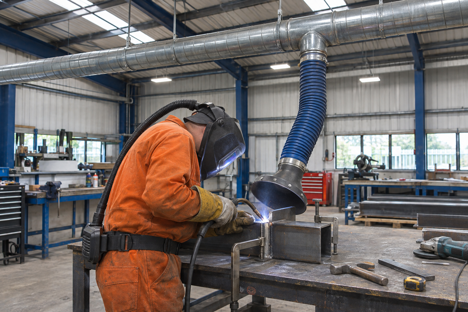
Local exhaust ventilation: user and condition check
24 checks · sound and fault examples
Follow hood, duct, filter, fan and indicator checks on the fixed welding-bench extraction example. A user check does not replace competent thorough examination and testing or prove capture at the real task.