SHARE Knowledge Hub
Electrical control measures, safe systems and inspection
Electrical safety depends on suitable design, protection, secure isolation and inspection that finds defects before people are exposed. A damaged conductor, failed protective device or unexpected supply can cause shock, arc injury or fire even where a test label is current. Work on or near electrical systems therefore needs competent planning, a dead-work preference and a verified hand-back.
Understanding Electrical control measures, safe systems and inspection
Electrical control measures, safe systems and inspection are the connected arrangements used to prevent people contacting dangerous electricity, prevent electrical equipment becoming dangerous and reduce the consequences of foreseeable failures. Electricity can cause electric shock, internal/electrical burns, thermal burns, loss of muscle control, respiratory or cardiac effects, arc-flash injury, fire, explosion and secondary injury such as a fall. HSE explains that severity depends on factors including voltage, body path, dampness and duration. The people at risk include users, electricians, contractors, cleaners, drivers, visitors, customers and the public.
Why this matters at work
Electrical current can heat tissue along its path and cause deep burns, sometimes with limited visible surface damage. Arcing can generate intense heat and light, rapidly causing serious burn injury, eye injury, hearing damage and ignition. Faulty equipment, overloading, damaged conductors, poor joints, water ingress, inappropriate cleaning, crushed cables, unsuitable supply or defective protective arrangements can also start fires. Static electricity can ignite flammable vapours or dusts in the right atmosphere even where it does not harm a person directly.
Process failure: Control is applied out of context | How control is lost: Office/low-risk approach is copied into wet, industrial, construction or public setting | Possible consequence: Shock, fire, equipment failure and unsafe reliance on weak control | Management measures assurance and recovery: Avoid: remove unsuitable activity/equipment; Limit scope: reduce voltage/harsh exposure; Restrict release: separate users/area and isolate faults; Management arrangements: task/environment risk assessment, suitable selection and inspection plan; Residual task protection: residual PPE; Implementation assurance: task coordinator verifies the work boundary and prevents user checks being extended into specialist electrical work.
How organisations manage this in practice
PAT is a descriptive term for a combined inspection and test; it is not a universal annual legal requirement. HSE states that annual PAT is not always necessary in low-risk environments and that most defects can be found visually, though some require testing. The PAT maintenance regime does not itself impose a universal label or test-log requirement, and these can be useful management tools. Other applicable duties may require records, including relevant work-equipment inspection records; a PAT FAQ does not remove them. The control objective is a maintenance regime that prevents danger: asset knowledge, user reporting, suitable inspection/testing, repair/removal, trend review and reassessment after change or event. Sources: HSE PAT FAQs; GB PUWER inspection; NI PUWER.
Distinguish user checks, formal visual inspection, combined inspection and test, fixed-installation inspection/testing, functional testing and electrical work. A user check is a simple pre-use observation by a trained user; it does not authorise opening equipment. Formal visual inspection is a competent examination of visible condition. Combined inspection and test may be called PAT; it requires suitable equipment and competence. Fixed-installation and specialist testing require a separate, task-specific technical process. A label can support management, but never proves present safety.
Inspect for cracked cases, missing covers, exposed cores, loose connections, overheating and water damage. Make defective equipment unavailable and obtain competent assessment. Do not bridge a fuse, fit a larger device or bypass an interlock because production needs the equipment. An RCD provides additional protection in relevant circumstances; it cannot make unsafe contact or an unsuitable installation acceptable. Retain design and maintenance information and review it when loads, use or the environment change. Verification should address the intended protective function, not merely whether the equipment runs.
Use the practical electrical control route
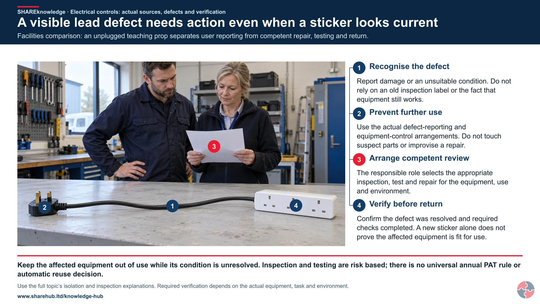
A tool has a current test label but its lead is freshly crushed. The user stops using it and reports the damage; the supervisor prevents reuse and arranges competent inspection and repair or replacement. The label records an earlier check and an RCD provides only part of the protection.
- Recognise the hazard — Identify shock, arc, fire and secondary injury mechanisms.
- Isolate and control the work — Secure every supply and stored-energy source and prove dead.
- Plan inspection and testing — Match maintenance to equipment, use, environment and defects.
- Manage an electrical contractor — Agree competence, interfaces and controlled hand-back.
Return the tool only after the competent person confirms the repair and appropriate checks, and the supervisor resolves the route or storage condition that damaged it. Record the defect, corrective action and release. Inspection and testing intervals follow risk and experience; this example creates no universal annual PAT rule.
Content amended 19 October 2026 by the SHARE Knowledge Hub editorial team. This records an editorial content change; the existing technical-review and approval status still applies.
Match the control to the failure it must prevent
An enclosure, cable condition, protective device and controlled work boundary perform different functions. Inspection and competent testing provide evidence about them; they are not interchangeable safeguards.

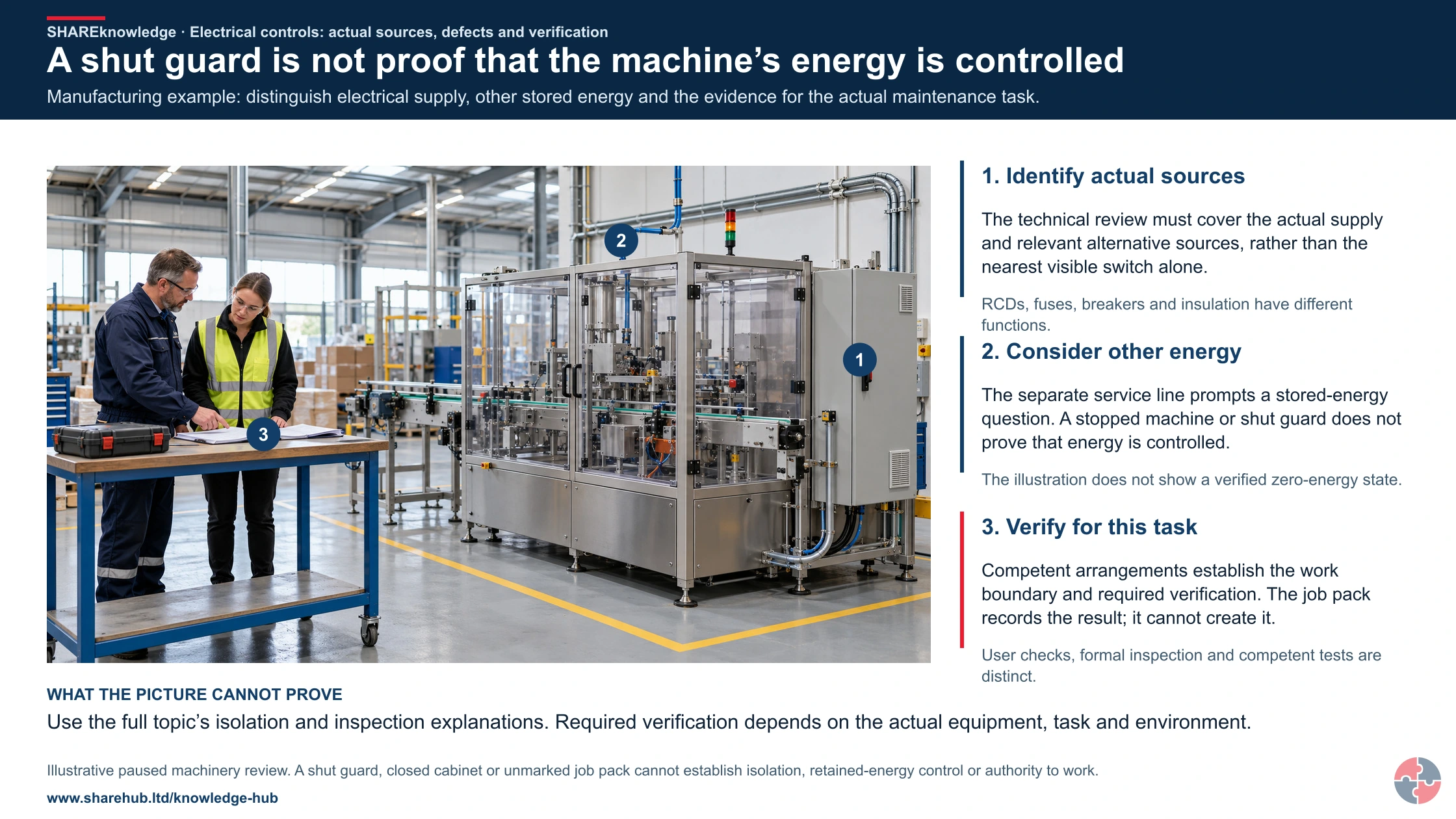
A shut guard is not proof that the machine’s energy is controlled
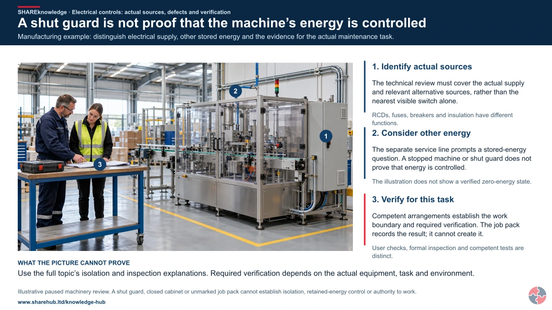
Full written explanation
Manufacturing example: distinguish electrical supply, other stored energy and the evidence for the actual maintenance task.
- Identify actual sources. The technical review must cover the actual supply and relevant alternative sources, rather than the nearest visible switch alone.
- Consider other energy. The separate service line prompts a stored-energy question. A stopped machine or shut guard does not prove that energy is controlled.
- Verify for this task. Competent arrangements establish the work boundary and required verification. The job pack records the result; it cannot create it.
Change the pathway
- Protection has limits. RCDs, fuses, breakers and insulation have different functions.
- No status from appearances. The illustration does not show a verified zero-energy state.
- No inspection shortcut. User checks, formal inspection and competent tests are distinct.
Evidence check: Use the full topic’s isolation and inspection explanations. Required verification depends on the actual equipment, task and environment.
Complementary user checks, competent inspection/testing and defect closeout
Primary references: HSE: electrical safe working practices, HSG85 · HSE: risk-based portable-equipment maintenance
Open the complete HD image (new tab)Download image
Complementary user checks, competent inspection/testing and defect closeout
Primary references: HSE: electrical safe working practices, HSG85 · HSE: risk-based portable-equipment maintenance

Physical protection
Assess enclosure, cabling, protective devices and access for the environment and task.
Inspection evidence
Set suitable user checks, inspection and testing based on risk, use, conditions and competent advice rather than a universal interval.
Failed or uncertain state
Remove affected equipment from unsafe use, obtain competent correction and verify the required evidence before return.
A test label, low voltage description or apparently sound enclosure cannot settle every electrical risk.
What electrical control sequence prevents exposure?
Start by removing unnecessary electrical exposure and selecting suitable equipment. Then protect conductors, secure and prove isolation for work, inspect for deterioration, and hand back only after competent verification.
Best-practice guide: Electrical control measures, safe systems and inspection
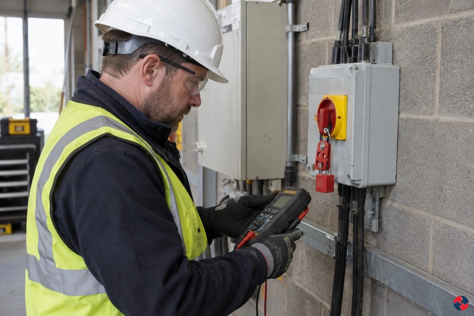
What electrical control sequence prevents exposure?
Start by removing unnecessary electrical exposure and selecting suitable equipment. Then protect conductors, secure and prove isolation for work, inspect for deterioration, and hand back only after competent verification. Electrical safety depends on suitable design, protection, secure isolation and inspection that finds defects before people are exposed.
Turn electrical control measures, safe systems and inspection knowledge into a decision
Electrical safety depends on suitable design, protection, secure isolation and inspection that finds defects before people are exposed. A damaged conductor, failed protective device or unexpected supply can cause shock, arc injury or fire even where a test label is current. Revised work pack, isolation and test record, briefing, certificate and defect closure.
A field decision from start to hand-back
Competent lead locates, isolates and proves the circuit dead at the work point; supervisor keeps other trades clear. Restore guards and supply only after people clear; give the client an updated circuit record.
Electrical harm mechanisms
Electric shock: Current passes through the body after contact with live parts. Electrical burns: Current heats tissue or arc energy burns skin and eyes. Loss of muscle control: Shock causes spasm, inability to let go or a fall.
Choose controls for electrical control measures, safe systems and inspection
Elimination: Use external diagnostics or remove the faulty equipment from use where that avoids exposed electrical work. Engineering controls: Use a suitable off-line test or replaceable module where it safely proves the fault without exposed live conductors. Engineering controls: Securely isolate relevant supplies, prevent reconnection and prove dead using the approved safe-isolation method. Engineering controls: Provide suitable enclosures, protective devices and test equipment for the actual circuit and installation. Administrative controls: Confirm circuit identity, competence, test scope and restart authority; separately justify and control any unavoidable energised test. Read the full control table for qualifications, ownership and verification. Use the actual task and applicable jurisdiction; existing technical approval remains unchanged.
Use the full electrical control measures, safe systems and inspection lesson
Use the full topic for the decision points, practical examples, detailed control tables and source scope. HSE guidance applies to Great Britain; use HSENI for the Northern Ireland route and the source’s stated jurisdiction. A simplified guide does not change the page’s technical-review or approval status.
Read all six steps as text
1. What electrical control sequence prevents exposure?
Start by removing unnecessary electrical exposure and selecting suitable equipment.
- Avoid / redesign: Use external diagnostics or remove the faulty equipment from use where that avoids exposed electrical work.
- Control the task: Securely isolate relevant supplies, prevent reconnection and prove dead using the approved safe-isolation method.
- Verify before release: If the hazardous step remains, keep it within the task assessment and select the stronger feasible remaining controls.
Start by removing unnecessary electrical exposure and selecting suitable equipment. Then protect conductors, secure and prove isolation for work, inspect for deterioration, and hand back only after competent verification. Electrical safety depends on suitable design, protection, secure isolation and inspection that finds defects before people are exposed.
Apply it: Which part of this plan would you check at the workface before authorising the task?
2. Turn electrical control measures, safe systems and inspection knowledge into a decision
Use the evidence to improve the actual work arrangement.
- Change at source: Use external diagnostics or remove the faulty equipment from use where that avoids exposed electrical work.
- Make it observable: If the hazardous step remains, keep it within the task assessment and select the stronger feasible remaining controls.
- Keep useful evidence: Revised work pack, isolation and test record, briefing, certificate and defect closure.
Electrical safety depends on suitable design, protection, secure isolation and inspection that finds defects before people are exposed. A damaged conductor, failed protective device or unexpected supply can cause shock, arc injury or fire even where a test label is current. Revised work pack, isolation and test record, briefing, certificate and defect closure.
Apply it: What evidence would show that the change improves this task, rather than only completing a record?
3. A field decision from start to hand-back
Example: a practical application of the existing topic lesson.
- Setting: the site team opens a refurbished wall where a cable route is uncertain.
- Act: Stop intrusive work, protect the area, identify all possible supplies and agree a revised method.
- Hold / review: Any unidentified conductor, unexpected voltage or changed scope stops the job.
Competent lead locates, isolates and proves the circuit dead at the work point; supervisor keeps other trades clear. Restore guards and supply only after people clear; give the client an updated circuit record.
Apply it: At which point would you hold this example, and what evidence would allow it to proceed?
4. Electrical harm mechanisms
Connect the task, the route to the person and the control that can fail.
- Electric shock: Current passes through the body after contact with live parts.
- Electrical burns: Current heats tissue or arc energy burns skin and eyes.
- Loss of muscle control: Shock causes spasm, inability to let go or a fall.
Electric shock: Current passes through the body after contact with live parts. Electrical burns: Current heats tissue or arc energy burns skin and eyes. Loss of muscle control: Shock causes spasm, inability to let go or a fall.
Apply it: Who could be exposed, including other trades, cleaners, maintainers and people nearby?
5. Choose controls for electrical control measures, safe systems and inspection
Start with the stronger practicable options and verify their effect.
- Elimination: Use external diagnostics or remove the faulty equipment from use where that avoids exposed electrical work.
- Engineering controls: Use a suitable off-line test or replaceable module where it safely proves the fault without exposed live conductors.
- Engineering controls: Securely isolate relevant supplies, prevent reconnection and prove dead using the approved safe-isolation method.
- Engineering controls: Provide suitable enclosures, protective devices and test equipment for the actual circuit and installation.
- Administrative controls: Confirm circuit identity, competence, test scope and restart authority; separately justify and control any unavoidable energised test.
Elimination: Use external diagnostics or remove the faulty equipment from use where that avoids exposed electrical work. Engineering controls: Use a suitable off-line test or replaceable module where it safely proves the fault without exposed live conductors. Engineering controls: Securely isolate relevant supplies, prevent reconnection and prove dead using the approved safe-isolation method. Engineering controls: Provide suitable enclosures, protective devices and test equipment for the actual circuit and installation. Administrative controls: Confirm circuit identity, competence, test scope and restart authority; separately justify and control any unavoidable energised test. Read the full control table for qualifications, ownership and verification. Use the actual task and applicable jurisdiction; existing technical approval remains unchanged.
Apply it: Which stronger option can be used here, and who will verify it before accepting the remaining risk?
6. Use the full electrical control measures, safe systems and inspection lesson
Follow the official sources below and retain the task-specific evidence.
- Official guidance: HSE - Introduction to electrical safety
- Official guidance: HSE - Electricity at work: safe working practices HSG85
- Task decision: Revised work pack, isolation and test record, briefing, certificate and defect closure.
Use the full topic for the decision points, practical examples, detailed control tables and source scope. HSE guidance applies to Great Britain; use HSENI for the Northern Ireland route and the source’s stated jurisdiction. A simplified guide does not change the page’s technical-review or approval status.
Apply it: Which official source and full-topic section will you use to resolve the next decision?
A safe method links design to the person at the work point: a labelled switch is insufficient if a second supply or stored charge remains. A supervisor should identify who can isolate, who proves dead, and what change would stop the task before tools approach conductors.
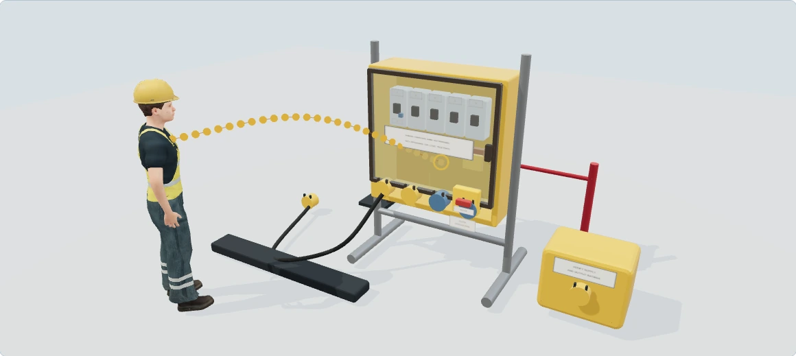

Temporary electrical supplies: follow the path to shock and fire
Explore how this equipment can harm its users and other people, then follow the practical measures that interrupt each pathway. This is a hazards and good-practice lesson; the separate checklist remains the pre-use/safety-check activity.
Hazards and good practice: learn what can hurt people during use, change and maintenance. Pre-use and safety checks stay in the separate checklist.
Checksheets and risk assessments
Equipment checksheets
- Site electrical distribution and RCD checks — 3D checks · Word · PDF
- Generators and temporary power supplies — 3D checks · Word · PDF
Risk assessment examples
Full written walkthrough — all 8 steps
1. Plan a suitable supply and work setting
What is happening: The distribution unit connects a source, protective devices, cables and equipment in a changing workplace.
How harm can occur: Unsuitable equipment or arrangements can expose users and other trades to shock, burns, arc or fire.
Best practice to apply: Use competent design and selection for the actual work, supply and environment; reduce avoidable electrical exposure.
Why this works: Suitable selection controls the hazard before a person has to work near the system.
Electrical hazards and risks · How should an electrical hazard be traced?2. Understand the contact pathway
What is happening: A live part or fault can connect the supply through a person to another conductive surface.
How harm can occur: Current through the body can cause serious injury; arcing can cause burns without the same direct contact.
Best practice to apply: Keep live parts enclosed and inaccessible and use the actual protective arrangements; never open this example as a user instruction.
Why this works: Preventing access interrupts contact; appearance and a healthy-looking cable do not establish an electrically safe system.
Electrical hazards and risks · Separate contact, arc, ignition and secondary injury3. Protect cables in the real work route
What is happening: Leads cross areas where vehicles, sharp edges, water and other operations may affect them.
How harm can occur: Damage or unsuitable routing can expose conductors, start a fire or create a trip leading to secondary injury.
Best practice to apply: Use appropriate routing and mechanical/environmental protection and respond to damage without makeshift live repairs.
Why this works: The route is part of the electrical risk, even when the connected tool has no visible defect.
Electrical hazards and risks · Why do wet environments increase electrical risk?4. Keep protective functions in context
What is happening: An RCD is one protective measure within a complete system, not permission to use a damaged supply.
How harm can occur: Some faults, contact conditions and other hazards are not removed simply because an RCD is fitted.
Best practice to apply: Use suitable competent selection, installation and verification; retain other required protection and the instructed user checks.
Why this works: A single protective device cannot stand in for correct system design and continued condition.
Electrical hazards and risks · How can the hierarchy of controls reduce risks while using portable power for a site repair?5. Maintain enclosure and access boundaries
What is happening: The sealed cover separates users from internal components and keeps the operating interface distinct.
How harm can occur: Opening or defeating protection can create access to energy that a routine user cannot safely assess.
Best practice to apply: Keep covers and restricted areas secure; refer faults or access needs to the responsible competent electrical person.
Why this works: Routine operation and intrusive electrical work require different competence and control arrangements.
Electrical hazards and risks · What training and competence are needed for electrical hazards?6. Recognise stop and isolation as different actions
What is happening: A switch indication or an inactive tool does not identify every source of electrical or other stored energy.
How harm can occur: A backup, battery, control circuit or other source can cause unexpected energisation or movement.
Best practice to apply: Plan dead work through the actual competent isolation, securing and verification procedure; this lesson does not teach live testing.
Why this works: System-specific identification and verification address sources that a simple stop can leave present.
Electrical hazards and risks · How can electricity injure the body, and why can a small mark hide a serious incident?7. Deal with an unsafe condition without touching danger
What is happening: A damaged supply or casualty may still be connected to continuing electrical danger.
How harm can occur: A rescuer or colleague can become a second casualty by approaching or touching too soon.
Best practice to apply: Keep people clear, use the site's emergency arrangements and have the continuing danger controlled; do not improvise a repair or rescue contact.
Why this works: Preventing additional contact protects people while competent emergency help and isolation are arranged.
Electrical hazards and risks · What are the secondary effects of electrical incidents?8. Return equipment only after competent resolution
What is happening: A replaced cable or reset trip does not by itself explain the fault or prove that the installation is suitable.
How harm can occur: The same fault can recur and harm the next user or an adjacent trade.
Best practice to apply: Record and restrict defective equipment, resolve the cause and have the necessary verification and handover completed.
Why this works: A verified repair and clear restrictions prevent a temporary reset being mistaken for a safe hand-back.
Electrical hazards and risks · How can the hierarchy of controls reduce risks while using portable power for a site repair?
Illustrative awareness learning. Geometry, colours and movement do not establish safe distances, capacity, exposure, isolation or work permission. Use the actual assessment, equipment information and competent arrangements.
The wider workplace has its own account and subscription access. Exploring this lesson does not grant access, record course completion or authorise work.
UK guidance for further reading
HSE: Temporary electrical suppliesHow can I practise this topic in 3D?

Electrical connections in the wet wash bay

A temporary generator has an improvised supply
A damaged supply cable remains connected
All related inspection points 12 across 8 locations
Garage workshop 1 inspection point
Construction site 2 inspection points
Warehouse walkabout 1 inspection point
Riverside Leisure 3 inspection points
Harvest & winter housing 2 inspection points
From flour to chilled despatch 1 inspection point
A safer place to call home 1 inspection point
Aerosystems Engineering 1 inspection point
Practice in the SHAREhub environment. Browser practice is separate from workplace competence and formal learning records.
What are the key points about electrical control measures?
The key points are suitability, protection, isolation, competence, inspection and maintenance.
Prevent contact with live parts
Use insulation, enclosure, guarding, locked panels and safe work methods to prevent people touching live conductors.
Select equipment for the environment
Wet, outdoor, dusty, damaged, cramped or conductive environments require stronger precautions than clean dry offices.
Protect conductors and circuits
Cables, plugs, sockets and fittings must be strong enough, protected from damage and correctly rated.
Use protective devices properly
Fuses, circuit breakers and RCDs must match the circuit, equipment and fault conditions.
Make dead and prove dead
Electrical work should normally be carried out dead with secure isolation and verification before work starts.
Inspect by risk, not habit
User checks, formal visual inspection and electrical testing should be based on risk, not a sticker culture.
What do electrical control measures, safe systems and inspection mean?
They mean choosing, using, maintaining and checking electrical equipment so it does not create danger.
Electrical safety has two sides. The first is engineering: equipment must be suitable, robust, insulated, enclosed, earthed, protected and correctly installed. The second is management: people need safe systems, competence, supervision, isolation procedures, inspection regimes, defect reporting and emergency arrangements.
A good assessment asks how someone could be exposed to electricity. Could a worker touch a live part? Could a damaged cable make a metal casing live? Could moisture reduce body resistance? Could a wrong fuse allow a cable to overheat? Could a circuit be re-energised during maintenance? Could a contractor drill into hidden wiring or excavate into a buried cable?
The answer should then choose controls that break those exposure routes. Training helps, but it is weaker than selecting suitable equipment, enclosing live parts, locking off isolators, using reduced voltage on construction sites, protecting cables from damage and maintaining equipment before defects become dangerous.
| Control area | Purpose | Evidence |
|---|---|---|
| Equipment suitability | Select equipment fit for task, environment and duty. | Specification, procurement and inspection records. |
| Physical protection | Prevent contact with live parts and damage to conductors. | Enclosures, guards, cable protection and locked panels. |
| Electrical protection | Limit fault energy and disconnect unsafe circuits. | Fuses, breakers, RCDs, earthing and test records. |
| Safe systems | Control work on or near electrical systems. | Permits, RAMS, isolation and proof-dead evidence. |
| Inspection and maintenance | Find deterioration before danger occurs. | User checks, formal inspections, test records and defect closure. |
| Competence | Make sure people understand the risk and their limits. | Training, authorisation and supervision records. |
What harm can electricity cause?
Electricity can cause fatal shock, burns, arc injury, fire, explosion, loss of muscle control and secondary injuries.
HSE explains that electrical injury depends on the voltage, current path, duration of contact, frequency, body resistance, dampness and individual circumstances. A shock can stop the heart beating properly, prevent breathing, cause muscle spasms or cause someone to fall from height. Electrical burns can be deep and disabling because current heats tissue internally.
Electrical equipment can also start fires through overheating, poor connections, overload, damaged insulation or unsuitable equipment. In explosive atmospheres, even low-energy sparks can ignite vapours, mists, gases or dusts. That is why electrical controls link closely with fire risk assessment, DSEAR, maintenance and inspection.
| Harm route | How it occurs | Control focus |
|---|---|---|
| Electric shock | Current passes through the body after contact with live parts. | Insulation, enclosure, isolation, RCDs and competence. |
| Electrical burns | Current heats tissue or arc energy burns skin and eyes. | Dead work, barriers, arc controls and PPE where needed. |
| Loss of muscle control | Shock causes spasm, inability to let go or a fall. | Prevent contact and control work at height interfaces. |
| Fire | Faulty, overloaded or poorly maintained equipment overheats. | Correct rating, inspection, maintenance and load control. |
| Explosion | Electrical equipment ignites vapour, gas, mist or dust. | DSEAR assessment and suitable equipment selection. |
| Secondary injury | A worker falls, strikes machinery or reacts suddenly after shock/burn. | Task planning and safe work area control. |

How can electricity injure the body, and why can a small mark hide a serious incident?
Interactive anatomy · Electrical injury · Updated 2026-10-23
Electrical injury terms
A broad term for injury associated with electrical exposure.
An external current affecting the body.
Tissue injury caused by electrical heating.
Death from electric shock.
Health and Safety Executive: Electrical injuries · Health and Safety Executive: Selection and use of electric handlamps, PM38 · NHS: Burns and scaldsRead all anatomy and process explanations without the viewer
General occupational awareness of anatomy and incident mechanisms. A broad term for injury associated with electrical exposure. An external current affecting the body. Tissue injury caused by electrical heating. Death from electric shock. Electrical rescue, live testing, isolation or energised work instruction An energise-person control, contact timer, voltage or resistance input Safe current paths, survival percentages or shock-severity scores ECG interpretation, rhythm selection or AED shock decisions Medical or workplace clearance from a mark, diagram or feeling well The hazard-avoidance and medical-help panel is visible before model loading and quiz completion.
Nerve pathway
Nerves communicate using electrical and chemical signals. Nerves carry biological signals, and communication at the nerve-to-muscle connection helps activate muscle. The travelling cue is a simplified way of directing attention to that relationship. It does not show household current circulating through a person, and its colour, speed or brightness cannot be used to interpret nerve function or electrical injury. Alder Hey Children’s NHS Foundation Trust: Nerve service — normal nerve function · NHS: Lambert-Eaton myasthenic syndrome — normal nerve-to-muscle signalling · Oxford University Hospitals NHS Foundation Trust: Nerve Conduction Studies and Electromyography
Skeletal muscle
The nervous system normally coordinates muscle contraction. A slow hand movement demonstrates normal function; it does not imitate a casualty’s involuntary movements. Alder Hey Children’s NHS Foundation Trust: Nerve service — normal nerve function · NHS: Lambert-Eaton myasthenic syndrome — normal nerve-to-muscle signalling
Breathing muscles
Coordinated muscle activity helps move air into and out of the lungs. The diaphragm and chest movement belong to the respiratory lesson. This example shows no breathing-rate measurement. Cambridge University Hospitals NHS Foundation Trust: Breathing pattern disorders and physiotherapy — normal diaphragm role
Heart conduction
Coordinated electrical activity helps organise the heart’s pumping. A labelled sequence illustrates normal biological activation. It is not an ECG or a rhythm-interpretation exercise. St George’s University Hospitals NHS Foundation Trust: Catheter Ablation for Supra-Ventricular Tachycardia — normal electrical system · NHS 111 Wales: Cardiac Arrest
Skin contact region
Contact conditions influence how an electrical exposure affects the body. The marker identifies an example contact region. It does not calculate skin resistance or identify a safe point to touch. Health and Safety Executive: Electrical injuries · Health and Safety Executive: Electrical safety frequently asked questions
Internal tissue region
Electrical injury can extend beneath the visible surface. An electrical incident can cause effects below the surface, so visible appearance alone cannot describe the whole injury. This transparent region marks the subject of the explanation, rather than a measured boundary of damage. Its shape does not establish where current travelled or which tissues are unaffected; compare it with the selected mechanism caption. Health and Safety Executive: Electrical injuries · NHS: Burns and scalds · NHS 111 Wales: Burns and scalds — electrical burns
External source
The incident hazard comes from an electrical source outside the body. The generic equipment symbol is kept disconnected from the normal biological signalling diagram. Health and Safety Executive: Introduction to electrical safety
Illustrative exposure route
This broad region represents one possible exposure route. It cannot establish the actual route or outcome. There is no safe-path selector, voltage control or timed-contact exercise. Health and Safety Executive: Electrical injuries · Health and Safety Executive: Electrical safety frequently asked questions
Arc and thermal region
An arc or hot electrical equipment can cause injury. This separate incident panel is different from a simple through-body current diagram. No arc flash is animated. Health and Safety Executive: Electrical injuries · Health and Safety Executive: Introduction to electrical safety
Secondary injury
Loss of control can lead to falls or contact with nearby hazards. The neutral surrounding-hazard symbol recognises these injuries without staging a fall or body jerk. Health and Safety Executive: Electrical injuries · Health and Safety Executive: Introduction to electrical safety
Response boundary
Keep clear of unresolved electrical danger and get emergency help. Do not touch a person who may still be in contact with an electrical source. This node opens the safety panel, never a rescue activity. Health and Safety Executive: Introduction to electrical safety · Health and Safety Executive: Electricity — electric shock and overhead-line precautions · Health and Safety Executive: Emergency procedures
Open the complete process transcript
The process, step by step
Explore normal function
Start with the body’s own signalling: nerves communicate with muscles, breathing muscles move the chest, and organised activation coordinates the heart. Select one example at a time and read the associated label before changing systems. These are normal biological functions, not electricity from equipment moving through a person. The slow cues make the explanation easier to follow; they do not show a measured nerve signal, breathing rate or heart rhythm. This process sequence is a teaching route through the subject, not a simulation of an electrical accident. Alder Hey Children’s NHS Foundation Trust: Nerve service — normal nerve function · NHS: Lambert-Eaton myasthenic syndrome — normal nerve-to-muscle signalling · Cambridge University Hospitals NHS Foundation Trust: Breathing pattern disorders and physiotherapy — normal diaphragm role · St George’s University Hospitals NHS Foundation Trust: Catheter Ablation for Supra-Ventricular Tachycardia — normal electrical system
What to watch: Select the nerve, skeletal-muscle, breathing-muscle and heart labels individually, noticing that each belongs to a different normal biological example.
Why it matters: Normal signalling helps muscles work in a coordinated way. Keeping these biological examples distinct from the incident diagrams makes it easier to explain what an external electrical hazard can disrupt.
Explore this step: Explore one normal system, then explain its function before selecting a different system.
Locate the external hazard
Locate the generic electrical-source symbol outside the body and compare it with the normal biological labels. It represents an external workplace hazard, not the source of ordinary nerve or heart signalling. The model keeps the equipment symbol separate and does not energise the silhouette when a learner selects it. This step establishes the context before the different injury mechanisms are discussed. A picture of equipment cannot show whether real equipment is safe. Use the label to identify the distinction, rather than imagining that the model is testing a circuit. Health and Safety Executive: Introduction to electrical safety · Health and Safety Executive: Emergency procedures
What to watch: Locate the external-source symbol and the response-boundary label, then compare their positions with the normal body-system labels.
Why it matters: An external electrical supply is a hazard that requires competent control. Separating it from biological signalling avoids implying that a normal nerve pathway describes a safe route for electrical current.
Explore this step: Identify which labels describe the body and which identify the external hazard or safety boundary.
Choose an incident example
Choose one incident explanation: electric shock, electrical heating within tissue, or an arc and its thermal effects. These are different mechanisms and more than one may be relevant to an incident. Read the selected heading before examining the highlighted region so that the image and explanation remain connected. The model is a route through the concepts, not a calculation of current flow or injury severity. It provides no voltage control, safe-contact experiment or animated arc. Compare the labels to explain how the mechanisms differ without ranking an actual casualty’s injuries. Health and Safety Executive: Electrical injuries · Health and Safety Executive: Introduction to electrical safety
What to watch: Read the incident heading, then locate its contact, internal-tissue or arc-and-thermal label rather than combining every marker into one route.
Why it matters: Shock can disturb body function, while heating can injure tissue. An arc can cause thermal injury without being equivalent to the simple contact diagram; the examples can overlap in a real incident.
Explore this step: Compare two incident panels and describe the different mechanism named by each heading.
Explain possible effects
Read the caption beside the selected system and trace the labelled relationship being explained. Electric shock can interfere with muscle control, breathing or the way the heart beats; electrical heating can damage tissue. The highlighted region is a teaching focus, not a map of an individual’s injury. It cannot identify the actual route through the body or declare that an unhighlighted organ is unaffected. Compare the normal-function labels with the incident caption, keeping the possible effect separate from any claim about what has happened to a particular person. Health and Safety Executive: Electrical injuries · Health and Safety Executive: Electrical safety frequently asked questions
What to watch: Compare the breathing-muscle, heart and internal-tissue labels with the caption for the incident mechanism currently selected.
Why it matters: Interference with coordinated muscle or heart function can be serious even when an illustration shows little surface change. A teaching marker cannot determine which effects are present or absent in a real person.
Explore this step: Choose a system and describe its normal role before reading the possible effect in the incident caption.
Know the limits
Finish by comparing the questions the diagram answers with those it cannot answer. It can introduce normal signalling and distinguish several possible injury mechanisms. It cannot establish an actual exposure, the extent of damage, a safe electrical condition or medical clearance. A small-looking electrical burn or feeling well does not provide that clearance. The external-source and response-boundary labels keep these limits visible. Review them alongside the existing safety panel; completing this teaching route is not a rescue procedure, a clinical assessment or permission to resume the work. NHS: Burns and scalds · Health and Safety Executive: Electrical safety frequently asked questions · NHS 111 Wales: Burns and scalds — electrical burns
What to watch: Locate the internal-tissue and response-boundary labels, then compare the limits stated in their captions with the incident explanation.
Why it matters: Visible appearance alone cannot establish the seriousness of electrical injury. Keeping the model’s scope clear prevents an explanatory picture or completed activity being mistaken for evidence that a person or workplace is safe.
Explore this step: Name one question the model explains and one question that requires assessment beyond this teaching view.
Mechanisms and their limits
Electric shock: disruption of normal function External electrical current can interfere with muscle control, breathing or the heart’s organised activity. These are possible effects; the same diagram cannot predict the outcome of a real incident. An illustrative route does not show that a particular organ must or cannot be affected. No arbitrary arrhythmia, dramatic flatline, body jerk or calculated survival result is shown. Both alternating and direct current can be dangerous. The viewer offers no safe voltage or safe path. Health and Safety Executive: Electrical injuries · Health and Safety Executive: Electrical safety frequently asked questions
HSE: prevent electrical injury
Electrical heating: injury beneath the surface Current passing through tissues can generate heat and cause burns beneath the skin. A small visible mark is not enough to judge the internal effects. Not every shock produces extensive burns. The marked region is illustrative, not a reconstructed path, calculated burn depth or severity score. An electrical burn needs emergency medical assessment even if it appears small. Feeling well or selecting a similar image does not provide workplace or medical clearance. Health and Safety Executive: Electrical injuries · NHS: Burns and scalds · NHS 111 Wales: Burns and scalds — electrical burns
NHS: electrical burns need emergency care
HSE: electrical injury mechanisms
Arc, heat and secondary injury Arcing and hot electrical equipment can injure people without the event fitting a simple hand-to-foot contact story. Heat, fire or explosion and secondary falls or nearby machinery may add hazards. The diagram does not require a through-body route to recognise an arc or thermal hazard. Alternating and direct current equipment can both present hazards. This is an incident explanation, not a flash-energy calculation or permission to approach damaged equipment. Health and Safety Executive: Electrical injuries · Health and Safety Executive: Introduction to electrical safety · Health and Safety Executive: Electrical safety frequently asked questions
HSE: electrical hazards and controls
HSE: competent assessment of unsafe equipment
Electric shock: disruption of normal function — follow the anatomy
Look at: The contact route through the body, including nerves and muscle.
What changes: Electric current can interfere with normal nerve, muscle, breathing or heart activity.
Why it matters: A person may be unable to let go, collapse or develop a dangerous rhythm.
What to do: Keep clear, do not touch anyone still in contact with electricity, call 999 and follow competent site emergency arrangements.
Damaged portable equipment presents an unresolved electrical hazard
A worker finds damaged equipment near a damp work area; the exposure is a counterfactual failure of controls, not a rescue exercise. An acute incident is explained in 32 seconds without voltage, current or contact-duration inputs. The sequence sets no safe exposure or waiting time. Never touch a person or equipment while electrical danger is unresolved. The viewer cannot prove isolation or infer the actual current path or outcome.
Keep clear of the unresolved source Damaged equipment in a damp area is a stop-and-report situation. Do not touch a potentially live casualty; call appropriate help and use competent site emergency arrangements. Health and Safety Executive: Electrical safety frequently asked questions · Health and Safety Executive: Emergency procedures
What failed barriers could allow The counterfactual contact example marks an external source and possible exposure. It does not ask the learner to energise a person or select a supposedly safe route. Health and Safety Executive: Electrical injuries · Health and Safety Executive: Electrical safety frequently asked questions
Possible interference with normal function External current can affect muscle control, breathing or heart function. These are possible effects, not a prediction that every organ is involved or that a particular contact is survivable. Health and Safety Executive: Electrical injuries
Safety first, then urgent assessment Keep clear and obtain emergency help while danger remains. Only once the scene is safe does the separate unresponsive/abnormal-breathing CPR/AED guidance apply. Feeling well does not provide medical or equipment clearance. Health and Safety Executive: Electrical safety frequently asked questions · NHS: Burns and scalds · NHS 111 Wales: Cardiac Arrest · Health and Safety Executive: Emergency procedures
Electrical heating: injury beneath the surface — follow the anatomy
Look at: The tissue beneath the electrical contact points.
What changes: Current can generate heat inside the body as well as at the skin.
Why it matters: A small visible mark can conceal serious deeper injury.
What to do: Keep the scene safe; electrical burns need 999 or A&E assessment even when the visible mark is small.
A small external mark after an electrical incident
After an electrical incident, a worker has a small visible hand mark; the area must be made safe by competent arrangements. This is a possible injury explanation, not a burn-depth model or a simulation of tissue heating at a selected exposure time. Visible marks cannot establish the route or depth of internal injury. Not every shock produces the broad affected area used in this illustration.
Do not approach unresolved energy danger The incident is treated as an electrical emergency until the scene is safe. Keep clear, summon appropriate help and do not judge safety from a small mark. Health and Safety Executive: Electrical safety frequently asked questions · NHS: Burns and scalds
External current can heat tissues A broad translucent region represents possible tissue heating during contact. It is not a wire tracing the real route and it does not calculate dose from a contact point. Health and Safety Executive: Electrical injuries
An external mark may understate injury The selected region separates possible internal effects from the skin marker. Size or appearance of the mark cannot clear the person or tell the learner what tissues were actually injured. Health and Safety Executive: Electrical injuries · NHS 111 Wales: Burns and scalds — electrical burns
Arrange medical assessment Use emergency help for electrical burns and follow live advice once it is safe to assist. Do not continue work or reassure someone simply because the mark is small; the activity gives no treatment or return-to-work clearance. NHS: Burns and scalds · NHS 111 Wales: Burns and scalds — electrical burns · Health and Safety Executive: Emergency procedures
Arc, heat and secondary injury — follow the anatomy
Look at: The skin and eyes facing the arc, and the worker’s surroundings.
What changes: An electrical arc releases intense heat; the event may also cause a fall or other trauma.
Why it matters: Burns and secondary injuries can occur without a current path through the body.
What to do: Control arc hazards, use competent isolation procedures and plan emergency response.
An electrical fault releases heat near a work area
A fault or overheated electrical component exposes people nearby to heat and possible secondary hazards. The short explanation omits flashes, noise and blast effects. It predicts no arc boundary, burn depth, safe distance or survival probability. Arc/thermal injury is separate from the through-body current example. A person need not supply a hand-to-foot contact story for the incident to be serious.
Treat the fault as unresolved danger Keep clear of faulty or overheated equipment and activate competent emergency arrangements. The example gives no permission for live inspection or repair. Health and Safety Executive: Introduction to electrical safety · Health and Safety Executive: Electrical safety frequently asked questions · Health and Safety Executive: Emergency procedures
Heat can be released without the chosen contact route The equipment-and-person schematic marks hot material or thermal exposure. No bright flash or energise-person action is used to teach the incident. Health and Safety Executive: Electrical injuries · Health and Safety Executive: Introduction to electrical safety
Possible thermal and secondary injury Heat may injure tissue, and a loss of control or sudden movement may lead to falls or contact with surrounding hazards. These possibilities remain separate from a reconstructed internal current path. Health and Safety Executive: Electrical injuries
Control the danger and get help Follow site emergency arrangements and obtain medical help for injuries once safe to assist. Competent investigation must address the fault; no visual improvement in the model clears the equipment or the worker. NHS: Burns and scalds · Health and Safety Executive: Electrical safety frequently asked questions · Health and Safety Executive: Emergency procedures
Read the practice situations and all answer explanations
EL-Q1: What can be concluded from the mark?
A colleague has had an electrical incident and has only a small visible mark.
It proves the event was harmless. — A small mark cannot rule out internal effects. Electrical burns need emergency care.
Internal effects cannot be judged from the mark; seek appropriate medical assessment. — Correct. Do not use appearance as reassurance. Keep the area safe and obtain appropriate medical help; an electrical burn requires 999 or A&E.
Select the closest route in the model to calculate survival. — The model cannot reconstruct the incident or predict survival. Seek appropriate help instead of matching an image.
Health and Safety Executive: Electrical injuries · NHS: Burns and scalds · NHS 111 Wales: Burns and scalds — electrical burnsEL-Q2: Which response avoids creating another casualty?
Someone may still be in contact with a live electrical source.
Touch them immediately to pull them away. — Do not touch them while the electrical danger is unresolved. You could also be injured. Call for emergency help.
Keep clear, call emergency help and follow competent site emergency arrangements. — Correct. Call 999 and explain that electricity is involved. Keep others clear and follow competent emergency arrangements; this lesson does not teach electrical rescue or isolation.
Use the viewer to find the safest current path. — There is no safe-path or rescue method in this viewer. Keep clear and get emergency help.
Health and Safety Executive: Introduction to electrical safety · Health and Safety Executive: Electricity — electric shock and overhead-line precautions · Health and Safety Executive: Emergency proceduresEL-Q3: What still needs consideration?
An arc incident happens without an obvious hand-to-foot contact route.
There cannot be an injury without that route. — A simple through-body route is not required for an arc/thermal injury or a secondary fall.
Arc, heat and secondary injuries. — Yes. Consider the incident hazards and obtain appropriate help rather than forcing the event into one current-path drawing.
Direct-current equipment cannot cause harm. — Both AC and DC equipment can be hazardous. Neither label provides reassurance.
Health and Safety Executive: Electrical injuries · Health and Safety Executive: Introduction to electrical safety · Health and Safety Executive: Electrical safety frequently asked questionsSources and how the model is made
The opening images are AI-generated anatomical illustrations. The interactive 3D models and labelled SVG diagrams use original procedural artwork. These teaching images are not medical scans or diagnostic tools. Source references support the learner explanations and do not grant artwork rights.
- Health and Safety Executive: Electrical injuries — Possible shock effects, deep tissue heating, loss of muscle control, thermal and secondary injuries; AC and DC hazards. No numerical voltage/contact-time thresholds transferred.
- Health and Safety Executive: Introduction to electrical safety — Contact, arcing, fire/explosion and secondary falls; suitable equipment and competent maintenance/assessment. No isolation or live-work procedure generated.
- Health and Safety Executive: Selection and use of electric handlamps, PM38 — Page 1 defines electrocution as death from electric shock; replaces the brief’s US terminology source. No equipment specification or voltage rule copied into this awareness lesson.
- NHS: Burns and scalds — Current page reviewed 31 March 2026: electrical burns require 999 or A&E. No chemical-skin or eye-irrigation timer substituted.
- Alder Hey Children’s NHS Foundation Trust: Nerve service — normal nerve function — Basic biological electrical signalling and motor/sensory roles only. No paediatric injury prognosis or treatment transferred to the occupational module.
- NHS: Lambert-Eaton myasthenic syndrome — normal nerve-to-muscle signalling — Normal nerve signalling followed by chemical communication to activate muscle. Disease mechanisms and treatment are outside this module.
- Oxford University Hospitals NHS Foundation Trust: Nerve Conduction Studies and Electromyography — Natural electrical signals in nerves and muscle activity. No diagnostic procedure, test voltage or stimulation activity reused.
- Cambridge University Hospitals NHS Foundation Trust: Breathing pattern disorders and physiotherapy — normal diaphragm role — Diaphragm movement and air movement during breathing only. No exercise programme, self-assessment or rate target reused.
- St George’s University Hospitals NHS Foundation Trust: Catheter Ablation for Supra-Ventricular Tachycardia — normal electrical system — Page 2 normal cardiac electrical activation coordinating contraction. Printed review date October 2026 needs recheck at sign-off. No clinical procedure, ECG or third-party artwork copied.
- Health and Safety Executive: Electrical safety frequently asked questions — AC/DC hazards, multifactorial outcome uncertainty and need for competent safety assessment. No safe-voltage, resistance, RCD guarantee or risk score imported.
- NHS 111 Wales: Burns and scalds — electrical burns — A small-looking electrical burn can be very damaging and needs immediate medical attention. No household separation/rescue procedure copied.
- NHS 111 Wales: Cardiac Arrest — Unresponsive and absent/abnormal breathing, gasping, immediate 999/CPR/call-handler/AED recognition pathway. Applies only after electrical danger is resolved. No clinical ECG decision or full CPR course.
- Health and Safety Executive: Electricity — electric shock and overhead-line precautions — Do not touch a casualty while electrical danger remains; stay clear and warn others; first aid requires training. No separation technique, escape manoeuvre or rescue distance imported.
- Health and Safety Executive: Emergency procedures — Competent emergency control, calling emergency services, site arrangements and no resumption while serious danger remains. No procedural isolation instruction generated.
Which fixed electrical controls prevent danger?
Fixed controls include suitable design, insulation, enclosure, conductor protection, earthing, bonding, segregation and emergency isolation.
Fixed electrical controls should be built into the installation before anyone relies on behaviour. Conductors should be strong enough and protected against mechanical damage, heat, vibration, moisture, chemicals and foreseeable wear. Panels and distribution boards should be closed, labelled and locked where needed. Cables should be routed to avoid crushing, abrasion, trip hazards and impact.
Earthing and bonding help ensure that exposed conductive parts do not remain at a dangerous voltage during a fault. Protective devices should disconnect the supply quickly enough to prevent danger. Emergency stop or isolation devices should be accessible and understood. In construction and harsh environments, reduced voltage systems and additional protection may be needed.
| Control | What it does | Common failure |
|---|---|---|
| Insulation | Prevents contact with live conductors. | Insulation becomes cracked, cut, crushed or heat damaged. |
| Enclosure | Keeps live parts inside panels, boxes and equipment casings. | Covers are missing, open or not secured. |
| Cable protection | Prevents mechanical damage to conductors. | Cables run across traffic routes or sharp edges. |
| Earthing and bonding | Provides a fault path and limits dangerous touch voltage. | Earth continuity is missing, broken or not tested. |
| Segregation | Separates electrical hazards from pedestrians, vehicles or other trades. | Switchrooms become storage or access is uncontrolled. |
| Emergency isolation | Allows rapid disconnection in an emergency. | Isolator is hidden, unlabelled, blocked or not understood. |
How do fuses, circuit breakers, RCDs and reduced voltage help?
Protective devices reduce the likelihood or consequence of faults, but they must be correctly selected, installed, tested and maintained.
Fuses and circuit breakers protect conductors and equipment from excessive current. They must be correctly rated; oversized protection can allow cables to overheat before the device operates. Residual current devices detect leakage current and disconnect supply quickly, which is valuable for portable tools, outdoor use and higher-risk environments, but they do not make unsafe work acceptable.
Reduced voltage systems are often used in construction because they reduce shock severity compared with ordinary mains voltage. Double-insulated equipment adds a further design layer by not relying on a protective earth, but the casing, cable and plug still need inspection and correct use. See HSE electrical equipment guidance
| Device/control | Function | Inspection point |
|---|---|---|
| Fuse | Melts under excessive current to disconnect a circuit. | Correct rating and no bypassing. |
| Circuit breaker | Disconnects under fault or overload conditions. | Correct type, rating and trip condition. |
| RCD | Trips when leakage current is detected. | Regular test and suitable sensitivity. |
| Earthing | Provides a low-resistance fault path. | Continuity and condition. |
| Double insulation | Provides two layers of insulation without relying on earth. | Casing integrity and cable condition. |
| Reduced voltage | Reduces shock risk in harsh or construction environments. | Correct transformer, plugs, leads and distribution. |
How should electrical isolation and proof dead be managed?
Electrical isolation should secure every source of energy, prevent re-energisation and prove the equipment dead before work starts.
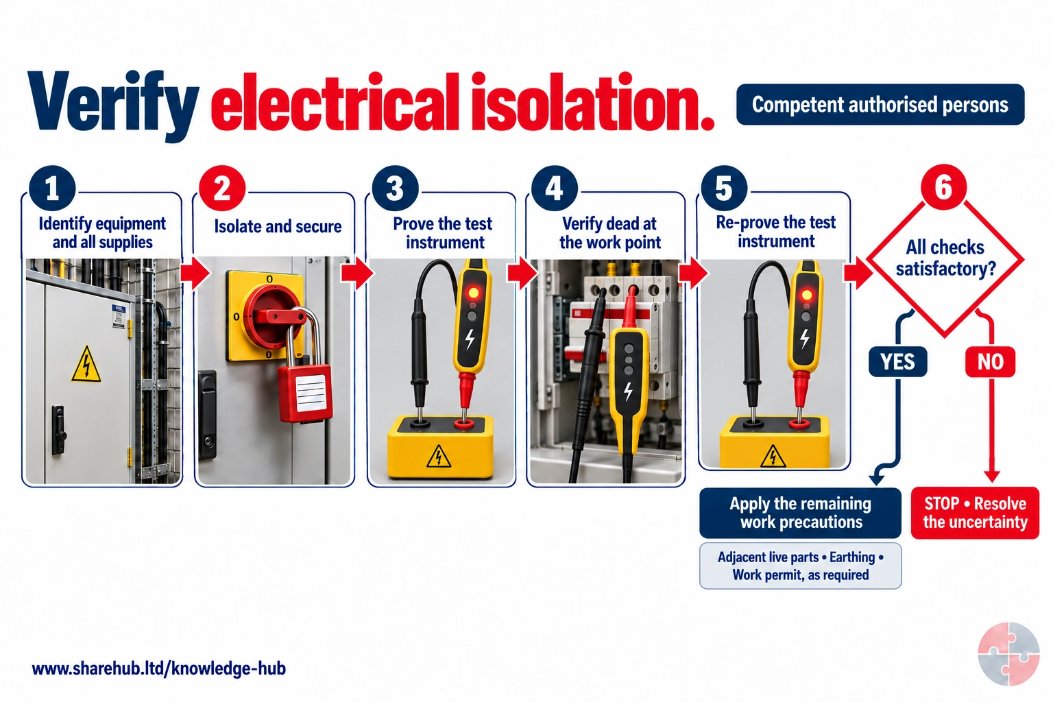
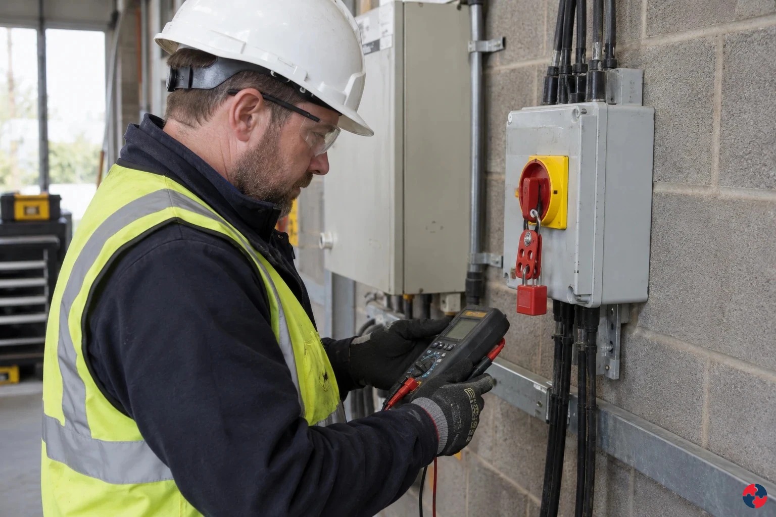
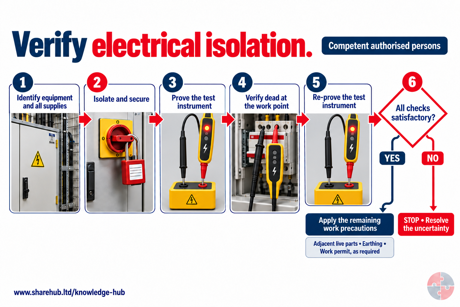
Identification of all supplies, securing the disconnection and proving dead at the work point are separate controls. The two-pole voltage detector is tested on a proving unit before and after use. The illustrated probe pair represents the verification step; a competent person must check every relevant supply conductor and combination required by the system.
Why is the voltage detector proved again after verifying dead?
To check that the detector remained functional during the verification. A failed instrument can give a misleading absence of voltage; the full required dead tests and remaining work precautions must also be completed.
Awareness schematic only, not authority or a complete method for electrical work. HSG85, GS38, suitable test equipment and a competent system-specific procedure govern all supplies, stored charge, test combinations, earthing, adjacent live parts and permits where needed.
Source guidance: HSE HSG85
Isolation is a life-saving control. The sequence should normally be: identify the equipment and supplies, switch off, isolate at a secure point, lock off, tag, prove the test device, test the circuit dead, prove the test device again and keep the isolation secure until work is complete. Where there are multiple workers, each person may need personal lock-off or a controlled group isolation system.
The isolation plan should consider alternative supplies, generators, UPS systems, solar PV, backfeeds, control circuits, stored energy, capacitors and incorrect drawings. Re-energisation should only happen after tools are removed, guards restored, people clear, permits closed and a competent person authorises hand-back.
| Step | Purpose | Evidence |
|---|---|---|
| Identify | Confirm the correct circuit, equipment and all energy sources. | Drawing, label check and competent confirmation. |
| Isolate | Disconnect supply at a suitable point. | Isolation record or permit. |
| Secure | Prevent deliberate or accidental re-energisation. | Lock, tag and key control. |
| Prove tester | Confirm test equipment works before testing dead. | Test process or record. |
| Prove dead | Confirm the equipment is de-energised. | Permit or work-pack confirmation. |
| Reinstate safely | Restore only when safe and authorised. | Handover and energisation record. |
At the work point, the competent worker must test the identified conductors with a suitable device, verify the device before and after the dead test, and retain control of the isolation. If the expected circuit cannot be identified or the test indicates voltage, stop and reassess rather than trying another breaker by guesswork. See HSE safe electrical work
When is live electrical work allowed?
Live work is only acceptable when dead work is unreasonable, live work is reasonable and precautions prevent injury.
HSE's position is clear: it is never absolutely safe to work on live electrical equipment. Live work should be challenged. It may be necessary for certain testing or fault diagnosis, but convenience, production pressure or lack of planning are not enough. If work can reasonably be done dead, it should be done dead.
Where live work is justified, the work needs a written method, competent people, suitable test equipment, restricted access, barriers, insulated tools, emergency arrangements, PPE where required and supervision proportionate to the risk. The decision should be authorised, not left to informal judgement at the point of work.
| Question | What a good decision includes | Stop-work trigger |
|---|---|---|
| Can the work be done dead? | Shutdown, isolation and alternatives considered. | Dead work rejected only for convenience. |
| Is live work reasonable? | The task genuinely requires energisation. | Work includes repair or alteration that could be done dead. |
| Are precautions suitable? | Barriers, tools, test equipment, PPE and supervision in place. | Missing equipment or unclear method. |
| Is competence proven? | People are trained, authorised and experienced for the task. | Competence assumed from job title. |
| Is the emergency plan clear? | Shock, burn, fire and rescue actions are briefed. | No one knows how to isolate or summon help. |
The three regulation 14 tests are cumulative: dead work must be unreasonable, the live task reasonable, and precautions sufficient to prevent injury. A measurement that needs energisation may be limited to a defined test; it does not justify live replacement of a component. Record the boundary, competent authorisation and return-to-dead-work point. See HSE regulation 14 guidance
What should an electrical safe system of work include?
An electrical safe system should define the task, hazards, controls, people, authorisation, emergency actions and evidence.
A safe system is not just a written method statement. It is the practical arrangement that makes the job safe in the field. It should tell people what equipment is involved, what is live or dead, what isolation has been applied, what remains hazardous, what tools and PPE are needed, what conditions would stop the job and who has authority.
For higher-risk work, the safe system may include permits, isolation certificates, switching schedules, restricted access, temporary barriers, test records, briefings and hand-back checks. For routine user activity, it may be simpler: visual checks, safe use instructions, defect reporting and immediate removal of damaged equipment.
| Element | What it should answer | Evidence |
|---|---|---|
| Task definition | What exactly is being done and where? | Work pack or RAMS. |
| Hazard boundary | What is live, dead, isolated, exposed or nearby? | Marked drawings and briefing. |
| Control measures | Which engineering, procedural and PPE controls apply? | Risk assessment and permit conditions. |
| Competence | Who can do, supervise and authorise the work? | Competence matrix and appointment records. |
| Change rule | What happens if conditions differ from the plan? | Stop-work and escalation procedure. |
| Emergency response | How are shock, burns, fire or rescue managed? | Briefing and emergency information. |
How should electrical inspection and testing be organised?
Inspection and testing should be risk-based and should combine user checks, formal visual inspection and competent electrical testing where needed.
The inspection regime should reflect the equipment and environment. A desktop computer in a clean office is lower risk than a 110V tool on a wet construction site, a pressure washer, a catering appliance, a welding set, a temporary distribution board or switchgear in a harsh industrial area. More damage-prone equipment needs more frequent checks.
User checks are powerful because they happen before use. Workers should look for damaged plugs, loose covers, exposed inner cores, crushed or taped cables, burn marks, overheating, missing guards, water exposure and unsuitable extension leads. Formal visual inspection and electrical testing are needed where risk assessment shows they add value.
| Layer | Who does it | What it checks |
|---|---|---|
| Pre-use user check | Trained user. | Obvious damage, overheating, cable condition and suitability. |
| Formal visual inspection | Competent appointed person. | Plug wiring, fuse rating, casing, lead security and environment. |
| Electrical test | Competent person with suitable equipment. | Earth continuity, insulation resistance, polarity and other relevant tests. |
| Fixed installation inspection | Competent electrical person. | Installation condition, protection, earthing, circuits and defects. |
| Switchgear maintenance | Competent specialist. | Condition, operation, protection, interlocks and fault risk. |
| Action close-out | Responsible manager. | Defects removed, repaired or risk assessed before use. |
The inspection interval follows equipment, use and environment, then changes when defects reveal a faster deterioration pattern. A portable-tool sticker is evidence of one past check, not permission to use a damaged lead today. Users remove suspect equipment from service; competent inspection and test resolve the defect before return.
What are the limitations of portable appliance testing?
PAT is only one possible part of maintaining portable equipment; it is not a substitute for risk assessment, user checks or safe use.
Portable appliance testing is often misunderstood. HSE guidance makes clear that the law requires electrical equipment to be maintained so as to prevent danger, but it does not require every item to be tested annually. A PAT sticker can create false confidence if the equipment is damaged the next day, used in the wrong environment or connected to an overloaded extension lead.
A better system uses risk-based maintenance. It considers how often equipment is used, who uses it, whether it is moved, where it is used, how likely it is to be damaged, the manufacturer's advice, previous defects and the consequence of failure. In many low-risk environments, user checks and formal visual inspection may be enough. See HSE PAT guidance
| Misconception | Better approach | Evidence |
|---|---|---|
| Every item needs annual PAT | Set frequency by risk and environment. | Risk-based inspection schedule. |
| A sticker proves safety | Check condition before use and remove damaged equipment. | Defect reporting and quarantine. |
| PAT covers fixed wiring | Fixed installations need separate competent inspection. | EICR or installation inspection record. |
| Anyone can repair defects | Repairs need competent people. | Repair record and competence evidence. |
| Office equipment is always safe | Low risk still needs visual checks and defect response. | User briefing and inspection record. |
How should overhead lines, buried cables and hidden services be controlled?
Overhead, underground and hidden electrical services should be located, avoided, isolated or protected before work starts.
Electrical danger is not always inside a plug or panel. Construction, maintenance, landscaping, lifting, excavation and refurbishment can expose people to buried cables, overhead power lines or hidden wiring in walls, floors and ceilings. These tasks need planning before work starts because the hazard may not be visible.
For buried services, use plans, site information, cable-avoidance tools, trial holes and safe digging methods. For overhead lines, use route planning, exclusion zones, barriers, goalposts, competent supervision and contact with the network operator where needed. For refurbishment, check drawings, use detection tools and treat unknown cables as live until proved otherwise. See HSE buried-service guidance
| Service risk | Control | Evidence |
|---|---|---|
| Buried electrical cable | Plans, locating equipment, trial holes and safe excavation. | Permit to dig and scan record. |
| Overhead power line | Exclusion zone, route plan, barriers and goalposts. | Lifting/traffic plan and briefing. |
| Hidden wiring | Drawings, detection tools and isolation before drilling/cutting. | Refurbishment work pack. |
| Temporary construction supply | Protected routing, RCDs, reduced voltage and inspections. | Site electrical inspection log. |
| Other contractors | Coordination so one trade does not expose another. | Daily briefing and permit board. |
What emergency arrangements are needed for electrical work?
Emergency arrangements should cover shock, burns, arc injury, fire, isolation, rescue and first aid without putting rescuers at risk.
Electrical emergencies require calm and safe response. People should not touch a casualty who may still be in contact with live electricity. The first priority is to make the situation safe by isolating power where possible, then summon help, provide first aid within competence and manage fire or evacuation if required.
Where higher-risk electrical work is planned, emergency controls should be briefed before work starts: location of isolators, who can operate them, first aid cover, fire extinguishers suitable for electrical risks, access for emergency services, communication and post-incident reporting.
| Issue | Control | Evidence |
|---|---|---|
| Shock casualty | Do not touch until supply is isolated or safe. | Briefing and first aid procedure. |
| Burns or arc injury | Use first aid and medical assessment routes. | First aid cover and emergency contacts. |
| Electrical fire | Isolate if safe and use suitable extinguishers. | Fire risk assessment and equipment checks. |
| Rescue | Avoid unplanned rescue that exposes others. | Rescue plan for high-risk work. |
| Reporting | Record incidents and dangerous occurrences where required. | Incident report and investigation. |
How can the hierarchy of controls prevent electrical contact during equipment fault diagnosis?
Use HSE’s hierarchy to eliminate or substitute a hazard where practicable, then apply engineering and administrative controls before relying on PPE. Check each chosen control against the actual task and stop when it fails.
Use HSE’s hierarchy of controls: eliminate or substitute the hazard where possible, then use engineering and administrative controls; PPE is the last resort. Apply the sequence to the task and verify that each chosen barrier works. HSE hierarchy of controls (official source).
Electrical safety is a strong example of why the hierarchy matters. The best control is often to remove the need for live work, design equipment so live parts cannot be touched, use reduced voltage in high-risk conditions and isolate securely before maintenance. PPE can be important for some tasks, but it should not be the first or only control.
The hierarchy should be applied at design, procurement, installation, use, maintenance and decommissioning. If the workplace keeps relying on signs, briefings and PPE while equipment is unsuitable or poorly protected, the risk is not being controlled well.
How can the ERICPD hierarchy of controls prevent electrical contact during equipment fault diagnosis?

| Control level | Control for this activity | Owner and verification | Stop / restart decision |
|---|---|---|---|
| Eliminate | Use external diagnostics or remove the faulty equipment from use where that avoids exposed electrical work. | Task owner verifies that the proposed change removes the named hazardous step, including foreseeable cleaning, maintenance and work transferred elsewhere. | If the hazardous step remains, keep it within the task assessment and select the stronger feasible remaining controls. |
| Reduce, including substitution | Use a suitable off-line test or replaceable module where it safely proves the fault without exposed live conductors. | Competent task/process owner validates suitability, compatibility and new hazards against the actual operating requirements before the alternative is adopted. | Reject an alternative if its performance is unproved or its new hazards are unresolved. |
| Isolate | Securely isolate relevant supplies, prevent reconnection and prove dead using the approved safe-isolation method. | Supervisor checks the actual boundary, affected people and connected work; verify separation or isolation before allowing access. | Hold or stop for uncertain circuit, unexpected voltage or an unapproved need for live access. |
| Control: physical safeguards | Provide suitable enclosures, protective devices and test equipment for the actual circuit and installation. | Competent equipment/process owner checks circuit identity, all supplies, safe isolation and suitable test equipment. | Hold or stop for uncertain circuit, unexpected voltage or an unapproved need for live access. |
| Control: work method and response | Confirm circuit identity, competence, test scope and restart authority; separately justify and control any unavoidable energised test. | Supervisor confirms the work limits, competent cover, communication and stop/restart authority with the people doing this activity. | Hold work when the agreed limits, competent cover or effective communication cannot be maintained. |
| PPE | Specify electrical and other protection from the assessed task; PPE does not justify avoidable live work. | Assessor confirms whether personal protection is needed and checks suitability, condition, compatibility and any required fit evidence. | Do not use unsuitable protection or rely on PPE to continue after an essential source control fails. |
| Discipline | Check repairs, covers and protective functions and record the competent return-to-service decision. | Release only after competent electrical owner accepts completed tests and safe reinstatement. Retain verification and unresolved restrictions at handover. | Keep the task on hold until required reinstatement evidence and unresolved defects are accepted by the responsible owner. |
How can the ISO 45001 hierarchy of controls prevent electrical contact during equipment fault diagnosis?

| Control level | Control for this activity | Owner and verification | Stop / restart decision |
|---|---|---|---|
| Elimination | Use external diagnostics or remove the faulty equipment from use where that avoids exposed electrical work. | Task owner verifies that the proposed change removes the named hazardous step, including foreseeable cleaning, maintenance and work transferred elsewhere. | If the hazardous step remains, keep it within the task assessment and select the stronger feasible remaining controls. |
| Engineering controls | Use a suitable off-line test or replaceable module where it safely proves the fault without exposed live conductors. | Competent task/process owner validates suitability, compatibility and new hazards against the actual operating requirements before the alternative is adopted. | Reject an alternative if its performance is unproved or its new hazards are unresolved. |
| Engineering controls | Securely isolate relevant supplies, prevent reconnection and prove dead using the approved safe-isolation method. | Supervisor checks the actual boundary, affected people and connected work; verify separation or isolation before allowing access. | Hold or stop for uncertain circuit, unexpected voltage or an unapproved need for live access. |
| Engineering controls | Provide suitable enclosures, protective devices and test equipment for the actual circuit and installation. | Competent equipment/process owner checks circuit identity, all supplies, safe isolation and suitable test equipment. | Hold or stop for uncertain circuit, unexpected voltage or an unapproved need for live access. |
| Administrative controls | Confirm circuit identity, competence, test scope and restart authority; separately justify and control any unavoidable energised test. | Supervisor confirms the work limits, competent cover, communication and stop/restart authority with the people doing this activity. | Hold work when the agreed limits, competent cover or effective communication cannot be maintained. |
| PPE | Specify electrical and other protection from the assessed task; PPE does not justify avoidable live work. | Assessor confirms whether personal protection is needed and checks suitability, condition, compatibility and any required fit evidence. | Do not use unsuitable protection or rely on PPE to continue after an essential source control fails. |
| Administrative controls | Check repairs, covers and protective functions and record the competent return-to-service decision. | Release only after competent electrical owner accepts completed tests and safe reinstatement. Retain verification and unresolved restrictions at handover. | Keep the task on hold until required reinstatement evidence and unresolved defects are accepted by the responsible owner. |
Which legal duties apply to electrical controls and inspection?
Great Britain and Northern Ireland have separate electrical and general safety instruments. The duty is to prevent danger through suitable systems, competent work and maintenance; a PAT sticker or permit alone does not prove safety.
| Where | Instrument | Practical duty boundary |
|---|---|---|
| Great Britain | Electricity at Work Regulations 1989 | Construct, maintain and work on electrical systems so as to prevent danger. |
| Northern Ireland | Electricity at Work Regulations (Northern Ireland) 1991 | Apply the NI electricity-at-work duties, including control of live work. |
| Great Britain | Health and Safety at Work etc Act 1974 | Protect employees and others affected by work. |
| Northern Ireland | Health and Safety at Work (Northern Ireland) Order 1978 | Apply NI general employer and other-person duties. |
| Great Britain | Management Regulations 1999 | Assess risks and make suitable management arrangements. |
| Northern Ireland | Management of Health and Safety at Work Regulations (Northern Ireland) 2000 | Assess risks and make suitable NI management arrangements. |
Choose the row for the site location. Construction, supply-network and major-accident duties apply only where the described work or establishment falls within their scope. Match the actual circuit, process and activity to the instrument before writing a safe system.
What does HSE case learning show about electrical isolation?
HSE case learning shows that severe shock can occur when electrical supplies are not properly isolated and proved dead.
HSE's electrical isolation case study describes an electrician receiving a severe shock during building refurbishment when the supply had not been properly isolated. HSE's learning is direct: electrical supplies should be made dead and proved dead before work starts, and the method of isolation should prevent inadvertent or deliberate re-energisation.
This matters because many electrical incidents are not caused by a lack of awareness that electricity is dangerous. They are caused by weak control of ordinary steps: incomplete planning, no management system, poor isolation, no proof-dead verification, missing supervision or assumptions that someone else has made it safe.
What should an electrical controls risk register include?
The risk register should describe credible electrical failure scenarios, controls, owners and evidence.
A useful electrical risk register is scenario-based. Instead of broad entries such as 'electricity', it should describe how harm could occur: worker plugs damaged tool into wet area; contractor opens panel without proof dead; temporary construction lead is crushed by vehicle; office extension leads are overloaded; forklift strikes charging cable; worker drills into hidden wiring.
Each entry should identify the controls that prevent contact or fault, the evidence that proves maintenance and inspection, and the trigger for review after change, defect, incident or new equipment.
| Scenario | Controls | Evidence |
|---|---|---|
| Damaged portable tool used outdoors. | Pre-use checks, RCD, suitable IP rating and repair quarantine. | User checklist and defect log. |
| Circuit worked on while still live. | Isolation, lock-off, proof dead and authorised person control. | Permit and isolation record. |
| Temporary supply damaged by vehicles. | Cable route protection, barriers and daily inspection. | Temporary electrical inspection log. |
| Overloaded sockets in office. | Socket provision, no unfused adaptors and user briefing. | Inspection findings and action closure. |
| Excavator contacts buried cable. | HSG47 planning, drawings, locating and trial holes. | Permit to dig and service-locate record. |
| Switchgear deteriorates unnoticed. | Maintenance regime and competent inspection. | HSG230-based maintenance evidence. |
How could BuildOut Ltd manage electrical safe systems and inspection?

BuildOut Ltd would manage electrical safety through design review, temporary-supply control, contractor competence, inspections, isolation and handover evidence.
A visible lead defect needs action even when a sticker looks current
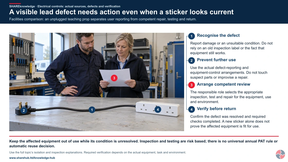
Full written explanation
The exact retained damaged-lead teaching scene is newly annotated for the controls topic. Four callouts identify the split outer sheath, unconnected UK plug, defect sheet and unused socket block. The review distinguishes removing suspect equipment from use, competent assessment and evidence of correction before return. It supplies no repair or electrical test technique.
Facilities comparison: an unplugged teaching prop separates user reporting from competent repair, testing and return.
- Recognise the defect. Report damage or an unsuitable condition. Do not rely on an old inspection label or the fact that equipment still works.
- Prevent further use. Use the actual defect-reporting and equipment-control arrangements. Do not touch suspect parts or improvise a repair.
- Arrange competent review. The responsible role selects the appropriate inspection, test and repair for the equipment, use and environment.
- Verify before return. Confirm the defect was resolved and required checks completed. A new sticker alone does not prove the affected equipment is fit for use.
When the evidence does not fit: Keep the affected equipment out of use while its condition is unresolved. Inspection and testing are risk based; there is no universal annual PAT rule or automatic reuse decision.
Who acts: Equipment user, responsible facilities/equipment manager and competent electrical inspection or repair role.
Changed workplace
Machine maintenance: Verify the actual sources, other energy and task boundary.
Facilities lead defect: Keep recognition/reporting separate from competent correction and verified return.
Evidence check: Use the full topic’s isolation and inspection explanations. Required verification depends on the actual equipment, task and environment.
Complementary user checks, competent inspection/testing and defect closeout
Primary references: HSE: electrical safe working practices, HSG85 · HSE: risk-based portable-equipment maintenance
Open the complete HD image (new tab)Download image
Complementary user checks, competent inspection/testing and defect closeout
Primary references: HSE: electrical safe working practices, HSG85 · HSE: risk-based portable-equipment maintenance
BuildOut Ltd
BuildOut Ltd works on construction and refurbishment projects where temporary electrics, drilling, hidden services, contractors, portable tools and client live systems can all create electrical risk.
BuildOut's procurement process requires suitable 110V or battery tools where appropriate, robust leads, RCD protection, weather-rated equipment and competent electrical contractors for temporary supplies. Site teams agree a temporary electrical plan before work starts, including distribution boards, cable routing, inspections, emergency isolation and protection from vehicles, water and mechanical damage.
Before intrusive work, supervisors check drawings, service information and scan requirements. Drilling, chasing and excavation near potential services is controlled through permits, locating equipment, marked-up drawings and trial holes where needed. Electrical panels, switchrooms and live client systems are kept out of casual access, and any work on circuits requires competent review, isolation and proof-dead evidence.
BuildOut uses three levels of monitoring. Frontline supervisors complete binary daily checks on leads, RCDs, damaged plugs, temporary supplies and access to electrical areas. Project managers and HSE advisers carry out second-line inspections that sample RAMS, permits, defect closure and contractor evidence. Periodic third-line audits review temporary electrical systems, contractor competence, documentation, certificates and whether recurring findings are being removed at source.
At handover, BuildOut collects inspection and test certificates, updated circuit information, labels, defect close-out, commissioning records and any remaining maintenance requirements. Repeated issues, such as damaged leads or blocked isolators, are reviewed through the risk register and procurement controls rather than treated as isolated housekeeping failures.
If BuildOut finds an unknown cable while opening a wall, the supervisor pauses intrusive work, protects the area and asks the competent electrical lead to identify and isolate the circuit. The work pack is revised and rebriefed before restart. At handover, the client receives the circuit change, test evidence and any residual restriction, rather than an unexplained certificate bundle.
A field decision from start to hand-back
Task material and setting: BuildOut opens a refurbished wall where a cable route is uncertain.
People and prerequisites: Installer, supervisor and competent electrical lead; drawings and locator evidence must be available.
Before: Stop intrusive work, protect the area, identify all possible supplies and agree a revised method.
During: Competent lead locates, isolates and proves the circuit dead at the work point; supervisor keeps other trades clear.
Hold or stop: Any unidentified conductor, unexpected voltage or changed scope stops the job.
Completion and hand back: Restore guards and supply only after people clear; give the client an updated circuit record.
Evidence: Revised work pack, isolation and test record, briefing, certificate and defect closure.
How should a fuel-site electrical inspection connect to the task?
Inspect the equipment and its operating environment, then follow the planned evidence link. A drawing or equipment label does not prove current protection integrity.
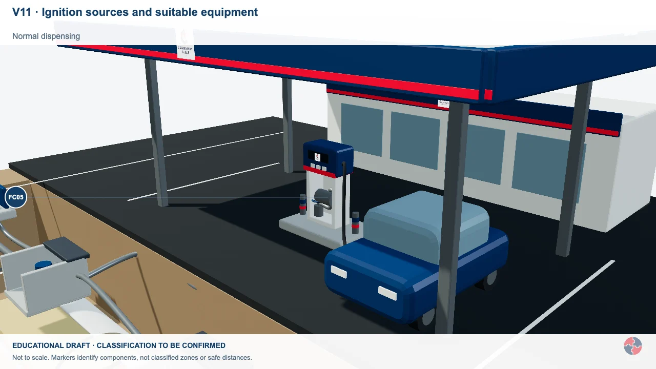
Ignition sources and suitable equipment
Electrical faults, hot work and other ignition sources matter where an explosive atmosphere could form.
Activity focus: Link equipment selection to the assessed atmosphere and actual dossier.
Contextual workplace scene. Use the task, control and evidence checks in this section; appearance alone does not establish safe conditions, individual health or approval.
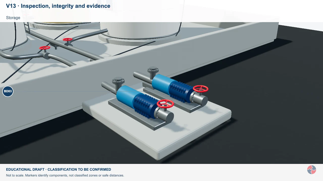
Inspection, integrity and evidence
A hose, tank or protective device has a safety purpose which depends on its condition and supporting checks.
Activity focus: Connect each identified defect to the responsible owner and appropriate operational decision.
Contextual workplace scene. Use the task, control and evidence checks in this section; appearance alone does not establish safe conditions, individual health or approval.
Educational illustration, not to scale. Coloured zones are teaching examples, not a site-specific hazardous-area classification.
What training and competence are needed?
Training should match the person's role, from user checks to authorised electrical work.
Electrical competence is role-specific. A worker using a drill needs to recognise damage and stop using unsafe equipment. A supervisor needs to know what a good temporary electrical setup looks like. A facilities manager needs to arrange risk-based inspection and competent repairs. An electrician needs technical competence, safe isolation, testing knowledge and authority limits.
The training system should avoid false confidence. Attendance at a course is not the same as competence. Competence should be checked through observed behaviour, authorisation, refresher training, supervision, work review and incident learning.
| Role | Learning | Demonstration | Assessor | Record | Reassess when |
|---|---|---|---|---|---|
| People nearby and new starters | Recognise damaged leads, barriers and alarm actions | Identify a defect and raise the alarm in a walk-through | Supervisor | Induction observation and report route | Changed area or missed report |
| Equipment users | Pre-use checks, suitability and stop-use rules | Inspect the actual tool and quarantine a defect | Task supervisor | Observed check and defect record | New tool or repeated defect |
| Electrical specialists | Isolation, proof dead, testing and task limits | Perform an observed isolation/test in scope | Competent electrical lead | Assessment and written authorisation | New system, method or incident |
| Supervisors and permit issuers | Plan the interface, challenge live work and release only when safe | Explain a changed-condition stop and restart decision | Electrical or process safety lead | Permit review and field observation | Scope change or poor permit |
| Managers, purchasers and designers | Specify suitable equipment and resource assurance | Trace a design or purchase decision to risk controls | Technical manager | Specification, review and action closure | New design or risk trend |
| Safety advisers and auditors | Sample legal scope, controls and barrier evidence | Trace a field defect through correction and learning | Independent competent reviewer | Audit trail and closed actions | New law, standard or repeat failure |
Competence is a demonstrated ability within a defined scope, not attendance alone. A supervisor should observe a relevant task or decision, record the assessor and limitation, and reassess when equipment, work conditions or an incident changes the need.
How does this topic support NEBOSH study?
This topic is central to NEBOSH learning because it links electrical hazards with practical controls and inspection evidence.
For the NEBOSH National General Certificate, this page aligns with electrical control measures, safe systems and inspection: protection of conductors, capability, fuses, earthing, isolation, double insulation, RCDs, reduced and low voltage systems, competent people, no live work unless justified, buried services, overhead-line protection, emergency procedures, user checks, formal inspection, testing and PAT limitations.
Scenario answers should be practical. If a question describes a construction site, include temporary supplies, reduced voltage, cable protection, RCDs and inspection. If it describes maintenance, include isolation, proof dead, competence and permit controls. If it describes an office, avoid overclaiming PAT and explain user checks, defect reporting and risk-based inspection.
How can management arrangements support this topic?
HSE’s Plan–Do–Check–Act guidance helps assign ownership, deliver controls, check evidence and improve weak arrangements. Apply the relevant legal duties and task-specific technical evidence separately.
Official management guidance: HSE Managing for health and safety (HSG65)
The linked catalogues confirm designation and publication status only. Exact licensed clause application remains for a competent, rights-cleared reviewer; this lesson states standard-level use without inventing a clause requirement.
What are the warning signs that electrical controls are failing?
Warning signs include damaged equipment, informal live work, weak isolation, repeated defects, poor records and over-reliance on PAT stickers.
Electrical controls often fail gradually before a serious incident. A taped cable, blocked isolator, overloaded extension, open panel, missing RCD test, repeated temporary repair or unknown circuit may be a weak signal. These should not be normalised.
The consequence can be immediate harm, but it can also be latent. Poor workmanship, wrong fuse ratings, missing labels or undocumented changes may sit hidden until a future worker opens the system.
| Warning sign | Possible consequence | Action |
|---|---|---|
| Damaged cable or plug remains in use | Shock, burns or fire. | Remove from use and repair/replace. |
| PAT stickers replace user checks | Damage after test is missed. | Train users and inspect by risk. |
| No proof-dead record | Work starts on live equipment. | Stop work and verify isolation. |
| Open or unlocked panels | Unauthorised contact with live parts. | Secure and investigate access control. |
| Extension leads overloaded | Overheating and fire. | Improve socket provision and load control. |
| Recurring inspection defects | Systemic weakness in procurement, use or maintenance. | Trend, rank and address root causes. |
What do the acronyms and key terms mean?
Electrical safety language should be explained so non-specialists can follow the controls.
| Term | Full expansion | Meaning here |
|---|---|---|
| AC | Alternating current | Current that repeatedly changes direction. |
| DC | Direct current | Current that flows in one direction; stored-energy sources still need isolation. |
| DSEAR | Dangerous Substances and Explosive Atmospheres Regulations | GB 2002 and NI 2003 regimes require assessment and control of dangerous-substance fire and explosion risk. |
| EAWR | Electricity at Work Regulations | The relevant GB 1989 or NI 1991 electrical work duties for the site. |
| EICR | Electrical Installation Condition Report | A report of inspection and testing of an electrical installation; the findings still need action. |
| GS38 | HSE Guidance Series 38 | HSE guidance on safe electrical test equipment and probes. |
| HSG85 | HSE Health and Safety Guidance 85 | HSE guidance on safe practices for work on or near electrical equipment. |
| IP rating | Ingress Protection rating | A code for an enclosure’s tested resistance to ingress of solids and water; suitability depends on the setting. |
| LOTO | Lockout and tagout | A system to secure isolation and identify control of the energy source. |
| PAT | Portable appliance testing | Examination and testing of portable equipment where a risk-based maintenance plan calls for it. |
| PPE | Personal protective equipment | Task-selected protection for residual risk; it does not remove electrical energy. |
| PTW | Permit to work | A documented authority coordinating defined high-risk work; it does not itself prove dead. |
| RCD | Residual current device | A device that disconnects on detected leakage current; additional protection, not permission for unsafe work. |
| SELV | Separated or safety extra-low voltage | A protective extra-low-voltage arrangement whose design and installation need competent verification. |
| UPS | Uninterruptible power supply | An alternative or stored-energy source that can keep equipment energised after the main supply is off. |
Which BuildOut documents support this topic?
Download individual editable BuildOut documents for this topic. Procedures and plans contain completed arrangements; forms, checklists, assessments, RAMS and permits are blank masters. Registers include separate worked examples.
| Document | Purpose and content | Editable download |
|---|---|---|
| Electrical installation, safe isolation and tool inspection procedure BOUK-PRO-ELEC · Completed worked example · v1.0 | Plan temporary distribution, verify installation integrity, control energisation and prevent unauthorised work. | Download DOCX Read preview |
| Temporary electrical installation and distribution plan BOUK-PLN-ELEC-01 · Completed worked example · v1.0 | Define suitable supply, protection, cable routes, checks and controlled alterations. | Download DOCX Read preview |
| Electrical isolation and re-energisation permit BOUK-PTW-ELEC-01 · Blank editable master · v1.0 | Identify isolation points, prove dead, lock off and control reinstatement. | Download DOCX Read preview |
| Electrical tools, leads and distribution inspection BOUK-CHK-ELEC-01 · Blank editable master · v1.0 | Set risk-based user checks and inspection/testing arrangements. | Download DOCX Read preview |
| Overhead-line and live-service proximity assessment BOUK-RA-ELEC-01 · Blank editable master · v1.0 | Plan avoidance, exclusion, utility coordination and safe work methods. | Download DOCX Read preview |
| Electrical installation verification and defect closeout BOUK-FRM-ELEC-01 · Blank editable master · v1.0 | Retain competent test/verification and restoration evidence. | Download DOCX Read preview |
| Electrical first/second fix and commissioning RAMS BOUK-RAMS-ELEC-01 · Blank editable master · v1.0 | Safe isolation, competence, temporary power, access and controlled energisation. | Download DOCX Read preview |
Review and adapt the documents for your organisation, activities and jurisdiction before approval and issue. Open the SHAREms management-system hierarchy to find each document under its parent policy.