Full public teaching and readers are free without an account. A free learner account is required for saved LMS progress and recorded assessment. Completion and any course-completion certificate depend on the configured LMS conditions. Full course outline and access routes.
Lesson 1
Define what each utility must deliver and to whom
Distinguish a live service from an available protective function.
Define what each utility must deliver and to whom
A utility can be energised while failing to meet the duty a safety measure depends on. In this fictional terminal, a water supply may show normal pressure yet lack the required flow at a distant user. An electric pump can be available at its switchboard while its supply route is exposed to the same event that creates the fire demand. Begin with the protected users and the assessed requirement, not the equipment list.
Ask what function is needed, how much delivery and for how long, under which credible conditions, and with what evidence. Values must come from the competent site design and performance standard. This course does not provide firewater sizing numbers, firefighting rates or a substitute engineering specification. The model shows connections for learning; it cannot measure reserve, pump performance, pipe losses or survival during a real emergency.
Trace a source-to-user chain on paper: supply, storage where provided, pumps, energy, controls, valves, distribution and the relevant delivery equipment. Add the people and procedures needed to recognise and manage a fault. Then ask which elements are shared. Several monitors fed by one unavailable main are not several independent water supplies, even if each has its own inspection sticker.
Use the fictional evidence pack to classify each statement as observed condition, claimed function or demonstrated duty. “Pump motor ran” is an observed condition. “Water available for the assessed incident” is a broader claim requiring connected evidence. Recording this distinction makes maintenance and operating discussions more precise and helps the decision owner state which activity must remain restricted while a critical part of the chain is uncertain.
Which services need the highest assurance?
Classify by credible harm and the safety function served, not by the utility name alone.
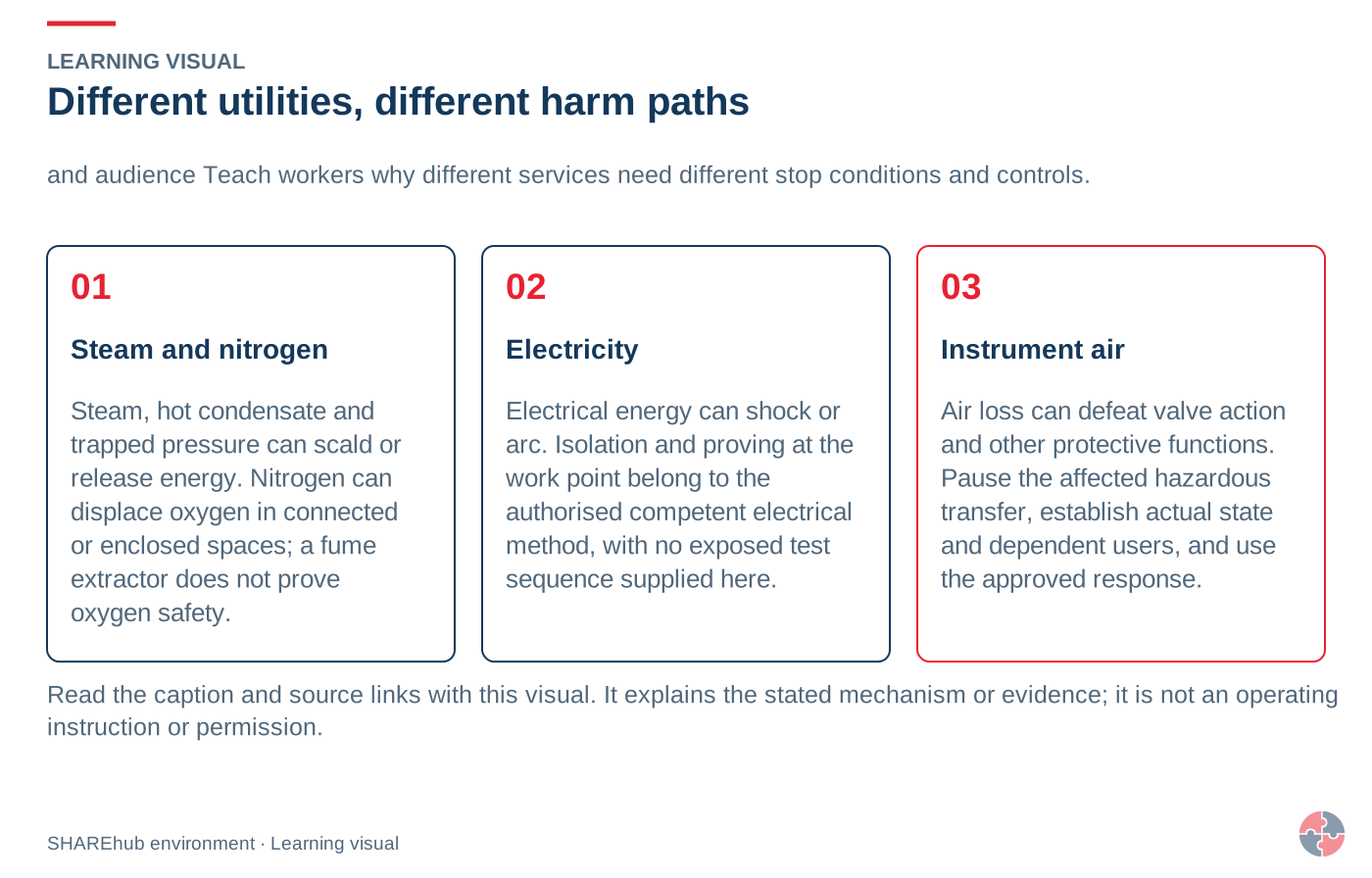
A compressor serving office tools is not equivalent to instrument air needed for a protective valve. A fire-water supply is only a credited barrier if it can deliver its required duty when demanded. Engineering sets site-specific capacity, autonomy, quality and test criteria; this page does not invent pressures, durations or test intervals.
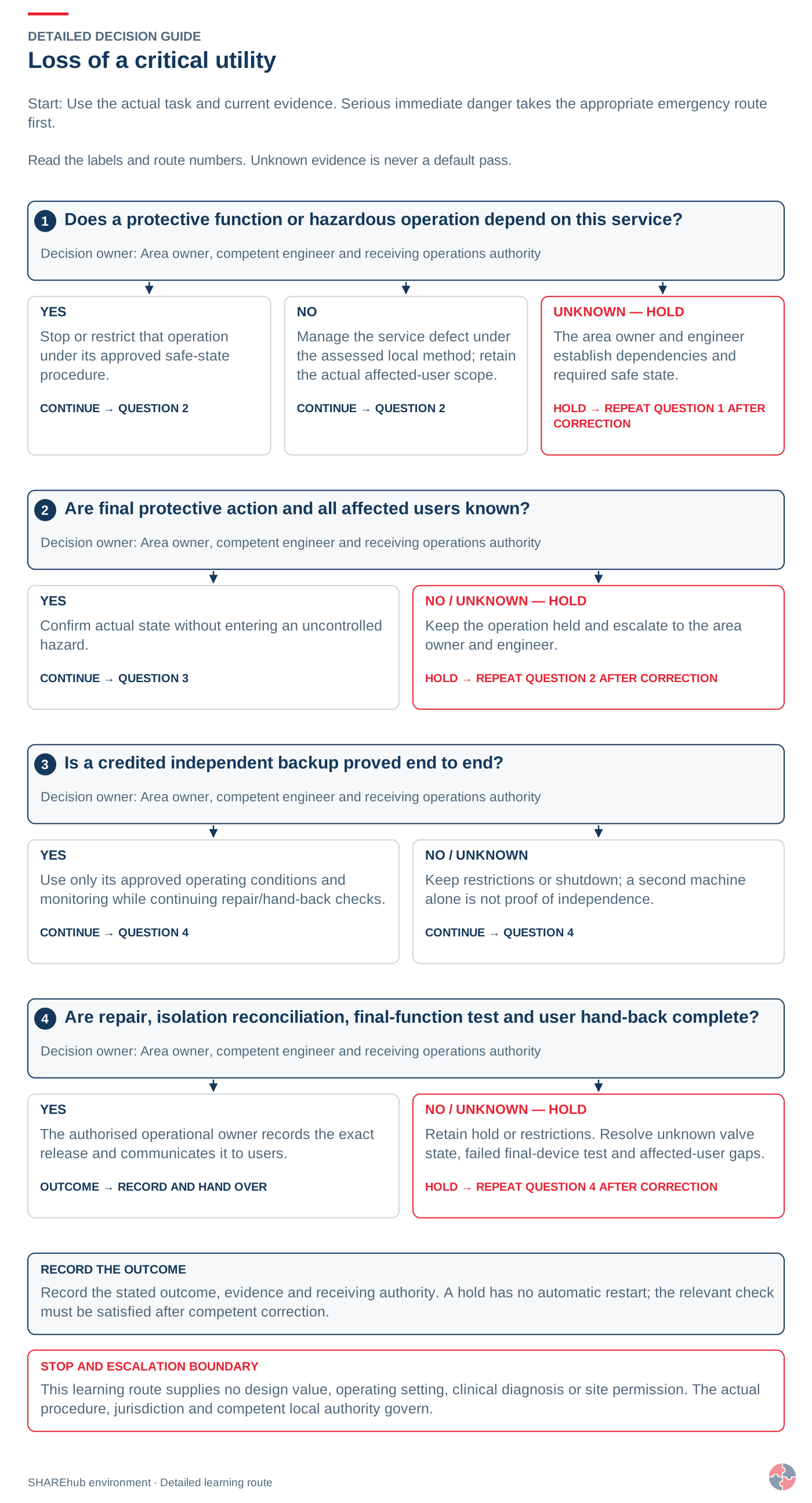
The utility board displays green pump indicators. The evidence pack does not identify the affected loading users, delivered duty or the behaviour of shared power during the assessed event.
Decision and explanation
What complete duty must the system deliver to the protected users under the credible demand?
Availability is a claim about a required function under relevant conditions. Establish that duty and the source-to-user chain before interpreting equipment indicators.
Look closer
Explore the numbered equipment and control points. Existing SHAREhub teaching schematic; illustrative and not to scale.Complete supply
Protection depends on the water source, power, starting, fuel and cooling arrangements for the required duty.
Shared dependencies
Electric and diesel labels do not prove independence. Challenge common causes, connected valves and unavailable services.
Delivery and retention
Verify distribution and impairments under the required duty. Plan contaminated runoff separately; static pressure alone does not prove delivery.
01 · Read the situation
The utility board displays green pump indicators. The evidence pack does not identify the affected loading users, delivered duty or the behaviour of shared power during the assessed event.
02 · Explain the principle
A utility can be energised while failing to meet the duty a safety measure depends on. In this fictional terminal, a water supply may show normal pressure yet lack the required flow at a distant user. An electric pump can be available at its switchboard while its supply route is exposed to the same event that creates the fire demand. Begin with the protected users and the assessed requirement, not the equipment list.
03 · Carry it into work
Availability is a claim about a required function under relevant conditions. Establish that duty and the source-to-user chain before interpreting equipment indicators.
Lesson 2
A starting pump and static pressure do not prove fire demand
Interpret diesel, electric and jockey-pump evidence at the correct scope.
A starting pump and static pressure do not prove fire demand
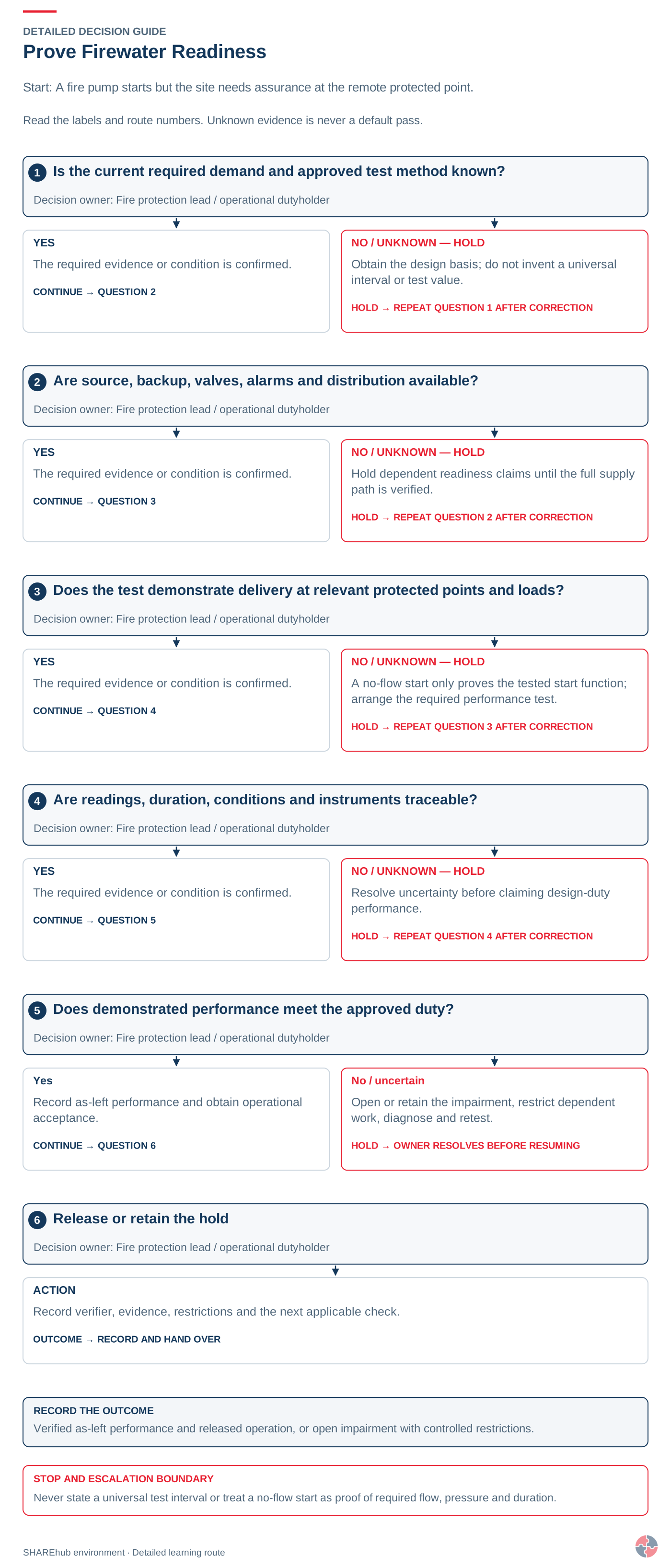
The diesel unit’s weekly start log answers whether the engine started under the recorded test. It does not alone prove that the complete supply can sustain the required emergency delivery. The fictional record leaves fuel readiness, starting batteries and delivered duty unresolved. Competent testing must address the approved requirement and conditions without creating an unsafe impairment while the system is being tested.
The electric-pump case asks a different question: can one supply or cable-route failure defeat both the duty arrangement and the claimed backup controls? Separate equipment names do not remove a common cause. Trace energy and control paths against the actual design assumptions. Learners should recognise and report the dependency; qualified specialists establish the required reliability, separation, testing and any accepted operating limitations.
The small jockey pump maintains pressure for its defined role. Its normal operation is not proof of main-pump firefighting capacity. Static pressure can exist with inadequate flow, a closed path or another limitation that only suitable system evidence resolves. Avoid inventing a field experiment by opening equipment; the competent test plan controls where water goes and how protection remains managed during testing.
For practice, compare three cards: engine-start record, normal pressure indication and suitable witnessed source-to-user performance evidence. State what each proves, its limits and the next question. If the wider duty remains unverified, escalate the impairment and apply the authorised restriction or compensating arrangement for affected operations. The learning objective is an honest availability statement, not a forced “pass” because someone has completed a routine checklist.
Why is firewater reliability critical?
Firewater reliability is critical because several active fire protection systems may depend on the same supply during the same emergency.
A firewater system includes more than a tank and pump. It may include water sources, suction arrangements, diesel and electric pumps, jockey pumps, pump houses, ring mains, sectional valves, hydrants, monitors, deluge valves, strainers, foam proportioners, test lines, standby power, fuel supplies and winterisation. A single closed valve, failed diesel start, blocked strainer or empty foam tank can defeat several downstream systems.
A no-flow pump start test may show that a pump starts, but not that water reaches the protected point at the required flow and pressure under credible simultaneous demand. The current design basis, manufacturer instructions and competent test plan determine what functional and flow evidence is needed. Check valves, hydrants, backup sources, alarms and known impairments as part of that assurance.
Sites also need to think about demand conflict. If sprinklers, monitors, deluge systems and emergency responders all draw from the same firewater network, the design must show that the system will not be starved during the credible scenario.
Firewater reliability checks
Firewater element
What can fail
Assurance evidence
Water source
Insufficient volume, poor replenishment, frozen supply or contaminated suction.
Tank level checks, capacity review, refill arrangements and inspection records.
Fire pumps
Failure to start, low flow, low pressure, fuel issue or maintenance defect.
Closed sectional valves, leaks, corrosion, pressure loss or poor labelling.
Valve line walks, lock/seal status, pressure tests and drawings.
Hydrants and monitors
Obstruction, damage, poor access, low pressure or poor reach.
Hydrant tests, monitor range checks, access inspections and responder drills.
Deluge and spray systems
Blocked nozzles, failed deluge valve, inadequate coverage or disabled actuation.
Functional tests, nozzle inspection, coverage checks and impairment records.
Common-cause dependencies
Power loss, flood, fire in pump house, cyber/control failure or multiple simultaneous demands.
Scenario testing, backup power checks, emergency exercises and design review.
Applied case
The diesel pump starts successfully, the electric pump depends on a shared vulnerable supply and the jockey pump maintains normal pressure. Dispatch treats the three facts as complete firewater proof.
Decision and explanation
The evidence is partial; the assessed complete duty and credible failure conditions still require competent verification.
Component observations have limited scope. Verify the actual required delivery and dependencies rather than treating starting or pressure as complete-system proof.
Look closer
Teaching graphic from the linked SHAREhub source section.01 · Read the situation
The diesel pump starts successfully, the electric pump depends on a shared vulnerable supply and the jockey pump maintains normal pressure. Dispatch treats the three facts as complete firewater proof.
02 · Explain the principle
The diesel unit’s weekly start log answers whether the engine started under the recorded test. It does not alone prove that the complete supply can sustain the required emergency delivery. The fictional record leaves fuel readiness, starting batteries and delivered duty unresolved. Competent testing must address the approved requirement and conditions without creating an unsafe impairment while the system is being tested.
03 · Carry it into work
Component observations have limited scope. Verify the actual required delivery and dependencies rather than treating starting or pressure as complete-system proof.
Lesson 3
Make every affected user visible during an impairment
Coordinate ring-main isolation with operations, permits and response.
Make every affected user visible during an impairment
A fire-main section can be isolated for a legitimate maintenance task while other teams continue relying on users it no longer supplies. The fictional loading controller’s screen has not been reconciled with the isolation register. A technically correct valve operation can therefore create an unsafe organisational assumption. Start by tracing the real boundary and all users affected by the unavailable section.
Declare the impairment through the authorised process before affected operations rely on the missing protection. The decision must identify exposure, restrictions or accepted compensating arrangements, responsible authority, duration and review points. It must reach operators, permit teams, maintenance and emergency coordinators as relevant. A notice pinned in the pump house may not inform the dispatcher who approves the next loading operation.
Simultaneous work can make the combined state worse than any single job suggests. A planned pump test, isolated ring-main section and temporary access obstruction can together affect response capability. Review their interaction before release. Avoid assuming an emergency service’s presence automatically compensates for unavailable fixed protection; the actual assessed capability and authorised plan must support any arrangement.
Restoration needs controlled evidence too. Account for work completion, correct valve status, temporary equipment and the specified functional verification. Communicate restoration and close the impairment only through the authorised handback. In the exercise, produce a simple affected-user map and a short status message: what is unavailable, which operations are limited, who owns the decision and what must happen next. This is more useful than stating that a maintenance job is “nearly finished”.
How should fire protection impairment be controlled?
Impairment control prevents a degraded fire protection system being treated as if it were still fully available.
A fire watch or temporary extinguisher does not automatically replace automatic detection, a sprinkler supply, deluge or exposure cooling. State exactly which scenario is no longer protected, what work must stop, who accepts residual risk, how people are informed and what test will end the impairment.
Impairment means a system is unavailable, partly unavailable or below its required performance. Examples include an isolated sprinkler zone, a disabled fire alarm detector, a drained fire main, a failed pump, out-of-service hydrants, foam concentrate unavailable, blocked access or maintenance work affecting a protected area.
The danger is normalisation. A short impairment can become accepted, a temporary isolation can be forgotten, or production can continue while a safety-critical mitigative barrier is unavailable. Impairments should therefore be risk assessed, authorised, time limited, communicated and compensated by temporary measures such as fire watch, reduced inventory, stopped hot work, standby resources or temporary detection.
The decision to continue operation during impairment should be made at the right level. Where the system protects a major accident scenario, the decision may need senior technical or operational approval, not only local maintenance sign-off.
Check combined impairments. A live firewater fault, disabled detection loop, unavailable foam stock or blocked responder access may affect the same scenario together. Before extending an impairment or changing plant, inventory, occupancy or work, reassess the combined loss of protection, renew the named approval and operating limits, and tell every affected shift and responder contact. Restore each dependent function and verify the complete barrier before closing the hold.
Fire protection impairment controls
Impairment control
What good looks like
Evidence
Identification
Any unavailable or degraded fire protection system is formally identified.
Impairment log, tag, alarm isolation record or defect report.
Risk assessment
The credible fire scenario and compensating measures are reviewed before continuing work.
Impairment risk assessment and temporary control plan.
Authorisation
The right level of management accepts the temporary risk.
Approval record with expiry date and operating limits.
Communication
Operators, maintenance, security, emergency team and affected contractors know the impairment.
Shift handover, permit notes, control-room log and emergency-team briefing.
Compensating measures
Extra fire watch, reduced inventory, stopped hot work, temporary equipment or restricted operations are applied.
Temporary control records and supervision checks.
Restoration and close-out
System is reinstated, tested and formally handed back.
Test record, close-out note and update to impairment register.
Applied case
A ring-main section is isolated for maintenance. The impairment register does not show it and the loading controller assumes every monitor and hydrant remains available.
Decision and explanation
Reconcile the actual boundary and affected users, declare the impairment and apply the authorised limits or alternative protection.
A ring layout alone does not prove an available route. Trace the real configuration, control the impairment and communicate the authorised operating decision.
Look closer
Teaching graphic from the linked SHAREhub source section.01 · Read the situation
A ring-main section is isolated for maintenance. The impairment register does not show it and the loading controller assumes every monitor and hydrant remains available.
02 · Explain the principle
A fire-main section can be isolated for a legitimate maintenance task while other teams continue relying on users it no longer supplies. The fictional loading controller’s screen has not been reconciled with the isolation register. A technically correct valve operation can therefore create an unsafe organisational assumption. Start by tracing the real boundary and all users affected by the unavailable section.
03 · Carry it into work
A ring layout alone does not prove an available route. Trace the real configuration, control the impairment and communicate the authorised operating decision.
Lesson 4
Control utility energy and verify the actual extinguishing medium
Fire classes and fire extinguishersFire classes · agent types · dangerous mismatches
Recognise the fuel. Read the extinguisher. Protect your escape.
People and escape first. Raise the alarm, follow the site’s evacuation plan and arrange the emergency call to 999. Only consider a small fire in its earliest stage if you are trained, authorised, have the correct equipment and a clear escape behind you. Smoke, spreading fire, uncertainty or an unsafe approach mean withdraw. Never delay escape to fetch an extinguisher.
UK awareness reference for common and specialist portable extinguisher families. Actual ratings, exclusions and manufacturer instructions govern each unit. Reading this guide is not practical training or permission to fight a fire. Fixed systems, hose reels and specialist industrial firefighting require their own assessed arrangements.
Terminal utilities: verify the actual medium and design duty. This portable guide is not a tank-fire or fixed-system operating procedure.
Fire classes: fuel, examples and the important distinction
Class
Fuel and examples
What matters
AClass A
Solid materials
Wood, paper, textiles and many solid plastics.
Usually forms an ember or char bed. Cooling matters; check the marked A rating.
BClass B
Flammable liquids
Petrol, solvents, diesel when burning, and liquefiable solids such as wax.
Fuel can spread across a surface. An unsuitable jet can spread burning liquid; solvent compatibility matters.
CClass C
Flammable gases
Propane, butane or methane.
Not a routine employee firefighting task. Knocking down flame while gas continues to escape can create an explosive cloud. Fuel isolation requires safe, competent action under the emergency plan.
DClass D
Combustible metals
Magnesium, sodium or metallic lithium.
Needs a metal-specific specialist agent. Ordinary ABC powder is not Class D powder.
FClass F
Cooking oils and fats
Hot oil in a fryer or pan.
Very hot oil can reignite. Water can produce violent steam expansion and eject burning oil.
LClass L
Lithium-ion batteries
A lithium-ion tool, e-bike or vehicle battery in thermal runaway.
Class L is included in BS ISO 3941:2026. Toxic or flammable gas, heat propagation and reignition need specialist planning. This is different from a metallic-lithium Class D fire.
Electrical equipment: Energised electrical equipment is an additional hazard, not a UK fire class called E. Do not import US Class C electrical or Class K cooking labels into this UK guide. Isolation, only where safe and authorised, does not remove the burning fuel or stored battery energy. Use the unit’s explicit electrical suitability and limitations.
Class L is the 2026 addition to the classification standard. Existing extinguisher labels and product test claims vary; a new class name does not certify every battery product.
Compare the classes · including lithium-ion batteries
Typical = usual application for the labelled family. If rated / unit limits = confirm the actual label and manufacturer conditions. No = not a normal selection for that hazard; specialist engineered arrangements are separate. This table cannot authorise firefighting.
* Electrical is an additional hazard, not a fire class. Gas-fire and battery-fire response require the assessed specialist plan. Scroll the table sideways on a narrow screen.
Typical portable-agent applications: always confirm the actual unit
Agent family
A · solids
B · liquids
C · gases
D · metals
Electrical*
F · cooking oil
L · Li-ion
Water
Typical
No
No
No
Unit limits
No
No
Water spray / water with additives
Typical
If rated
No
No
Unit limits
No
No
Foam
Typical
Typical
No
No
Unit limits
No
No
Water mist
Typical
If rated
No
No
Unit limits
If rated
Specialist plan
ABC dry powder
Typical
Typical
Specialist plan
No
Unit limits
No
No
BC dry powder
No
Typical
Specialist plan
No
Unit limits
No
No
Class D specialist powder
No
No
No
Exact metal
No
No
No
Carbon dioxide (CO₂)
No
Typical
No
No
Unit limits
No
No
Wet chemical
If rated
If rated
No
No
Unit limits
Typical
No
Clean agent / vaporising liquid
Unit rating
Unit rating
No
No
Unit limits
No
No
Battery-specific suppression products
If rated
No
No
No
Unit limits
No
Specified battery
Extinguisher types: uses and dangers
These are typical applications, not universal permissions. Check the label on the actual unit. Images are photorealistic teaching illustrations inspired by the referenced equipment; they are not photographs or certified product labels. Use Inspect the parts to explore the hardware. Band, nozzle and label details vary.
Common and specialist portable extinguisher families
Type and recognition
Typical rating and use
Wrong use: what can go wrong?
Parts in text
Cylinder
The pressure vessel holds the agent and propellant as designed. Report corrosion, dents or other damage. Do not open, refill or repair it as an awareness check.
Agent name and colour marking
Read the actual agent name, fire ratings, electrical warnings and instructions. Colour is a recognition aid; it does not prove suitability. The illustration is not an operating label.
Fixed carrying handle
The lower fixed handle supports the unit. It is different from the upper operating lever. The exact grip and operation belong in practical instruction for the model.
Operating / squeeze lever
The upper lever operates the discharge valve when the safety device is released. Do not squeeze or discharge a unit to test it during a routine visual check.
Safety pin and pull ring
The pin mechanically prevents accidental operation. A pin or ring that is missing, distorted or insecure needs reporting; its presence does not prove the unit is serviceable.
Tamper indicator / snap-lock seal
The breakable indicator or snap-lock seal shows possible disturbance. Designs can use a separate pin-retaining strap or a pin-mounted indicator. It is different from the mechanical safety pin and is not a theft lock. Report it if broken or missing.
Pressure gauge
On this stored-pressure example the gauge indicates pressure, not the mass of agent remaining. A pointer in the marked range does not prove the cylinder is full or the unit has passed its service checks.
Hose, nozzle or applicator
The flexible hose ends in the model’s discharge nozzle. The clip is for stowage; a hose being clipped in place is not a service check. Do not block, detach or test-discharge it during a visual inspection.
Base / protective boot
The boot protects the base on this example. Other models have a different foot arrangement or no separate boot. Check the approved mounting and access rather than guessing from the picture.
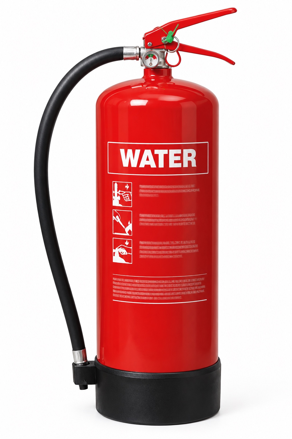
WaterRed / WATER marking
Normally A
Cools burning solid material such as paper, wood or fabric.
Check the limitation
Ordinary water is unsuitable for live electrical equipment, flammable-liquid pools, cooking oil and reactive metals: shock, spreading fuel or violent reaction can result.
Parts in text
Cylinder
The pressure vessel holds the agent and propellant as designed. Report corrosion, dents or other damage. Do not open, refill or repair it as an awareness check.
Agent name and colour marking
Read the actual agent name, fire ratings, electrical warnings and instructions. Colour is a recognition aid; it does not prove suitability. The illustration is not an operating label.
Fixed carrying handle
The lower fixed handle supports the unit. It is different from the upper operating lever. The exact grip and operation belong in practical instruction for the model.
Operating / squeeze lever
The upper lever operates the discharge valve when the safety device is released. Do not squeeze or discharge a unit to test it during a routine visual check.
Safety pin and pull ring
The pin mechanically prevents accidental operation. A pin or ring that is missing, distorted or insecure needs reporting; its presence does not prove the unit is serviceable.
Tamper indicator / snap-lock seal
The breakable indicator or snap-lock seal shows possible disturbance. Designs can use a separate pin-retaining strap or a pin-mounted indicator. It is different from the mechanical safety pin and is not a theft lock. Report it if broken or missing.
Pressure gauge
On this stored-pressure example the gauge indicates pressure, not the mass of agent remaining. A pointer in the marked range does not prove the cylinder is full or the unit has passed its service checks.
Hose, nozzle or applicator
The flexible hose ends in the model’s discharge nozzle. The clip is for stowage; a hose being clipped in place is not a service check. Do not block, detach or test-discharge it during a visual inspection.
Base / protective boot
The boot protects the base on this example. Other models have a different foot arrangement or no separate boot. Check the approved mounting and access rather than guessing from the picture.
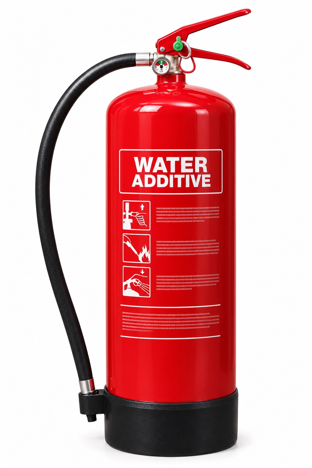
Water spray / water with additivesUsually red; read the agent name
A; B only if explicitly rated
Improved wetting or spray performance can help on the hazards stated on that model’s label.
Check the limitation
An additive does not make every water extinguisher safe for electricity, oils or reactive chemicals. Check the specific exclusions.
Parts in text
Cylinder
The pressure vessel holds the agent and propellant as designed. Report corrosion, dents or other damage. Do not open, refill or repair it as an awareness check.
Agent name and colour marking
Read the actual agent name, fire ratings, electrical warnings and instructions. Colour is a recognition aid; it does not prove suitability. The illustration is not an operating label.
Fixed carrying handle
The lower fixed handle supports the unit. It is different from the upper operating lever. The exact grip and operation belong in practical instruction for the model.
Operating / squeeze lever
The upper lever operates the discharge valve when the safety device is released. Do not squeeze or discharge a unit to test it during a routine visual check.
Safety pin and pull ring
The pin mechanically prevents accidental operation. A pin or ring that is missing, distorted or insecure needs reporting; its presence does not prove the unit is serviceable.
Tamper indicator / snap-lock seal
The breakable indicator or snap-lock seal shows possible disturbance. Designs can use a separate pin-retaining strap or a pin-mounted indicator. It is different from the mechanical safety pin and is not a theft lock. Report it if broken or missing.
Pressure gauge
On this stored-pressure example the gauge indicates pressure, not the mass of agent remaining. A pointer in the marked range does not prove the cylinder is full or the unit has passed its service checks.
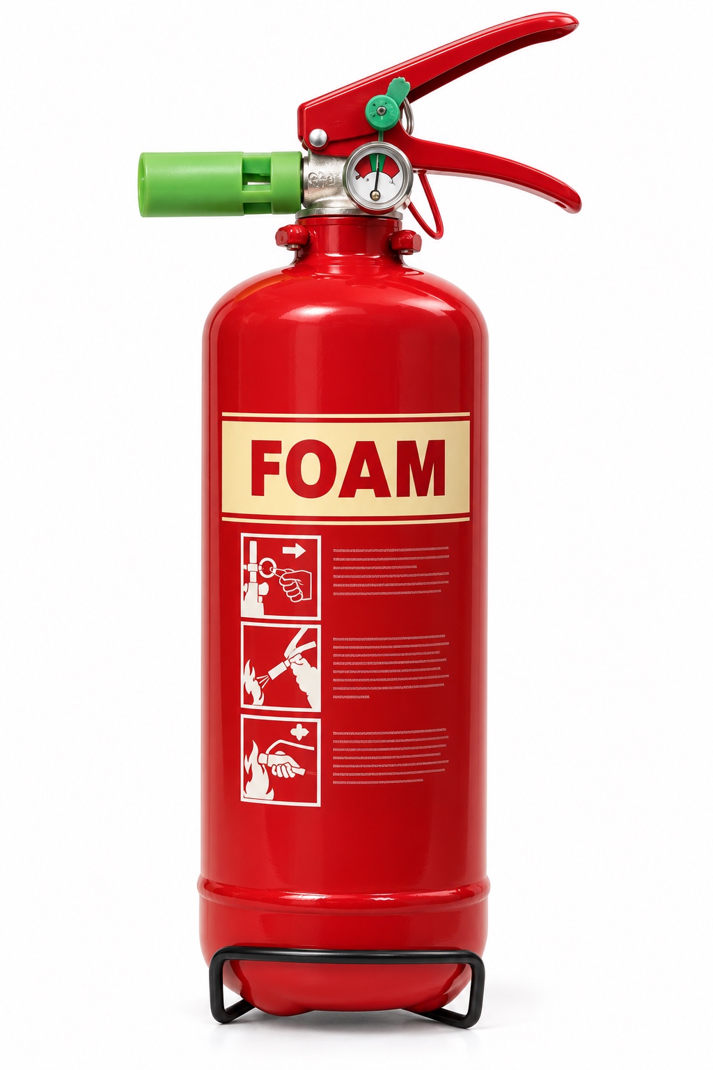
Direct spray nozzle
This compact foam example has a nozzle attached directly to the valve. Larger units may have a hose. Recognise the actual discharge arrangement and use only the approved agent and instructions.
Base / protective boot
The boot protects the base on this example. Other models have a different foot arrangement or no separate boot. Check the approved mounting and access rather than guessing from the picture.
FoamCream panel / FOAM
Commonly A and B
Cools and forms a surface blanket on suitable liquid fires. The agent must suit the actual fuel; some alcohols need alcohol-resistant foam.
Check the limitation
Ordinary foam is not a general answer for live electricity, cooking oil or metal fires. Unsuitable foam may break down on a solvent; a jet can spread fuel. Free-flowing fuel needs specialist response.
Parts in text
Cylinder
The pressure vessel holds the agent and propellant as designed. Report corrosion, dents or other damage. Do not open, refill or repair it as an awareness check.
Agent name and colour marking
Read the actual agent name, fire ratings, electrical warnings and instructions. Colour is a recognition aid; it does not prove suitability. The illustration is not an operating label.
Fixed carrying handle
The lower fixed handle supports the unit. It is different from the upper operating lever. The exact grip and operation belong in practical instruction for the model.
Operating / squeeze lever
The upper lever operates the discharge valve when the safety device is released. Do not squeeze or discharge a unit to test it during a routine visual check.
Safety pin and pull ring
The pin mechanically prevents accidental operation. A pin or ring that is missing, distorted or insecure needs reporting; its presence does not prove the unit is serviceable.
Tamper indicator / snap-lock seal
The breakable indicator or snap-lock seal shows possible disturbance. Designs can use a separate pin-retaining strap or a pin-mounted indicator. It is different from the mechanical safety pin and is not a theft lock. Report it if broken or missing.
Pressure gauge
On this stored-pressure example the gauge indicates pressure, not the mass of agent remaining. A pointer in the marked range does not prove the cylinder is full or the unit has passed its service checks.
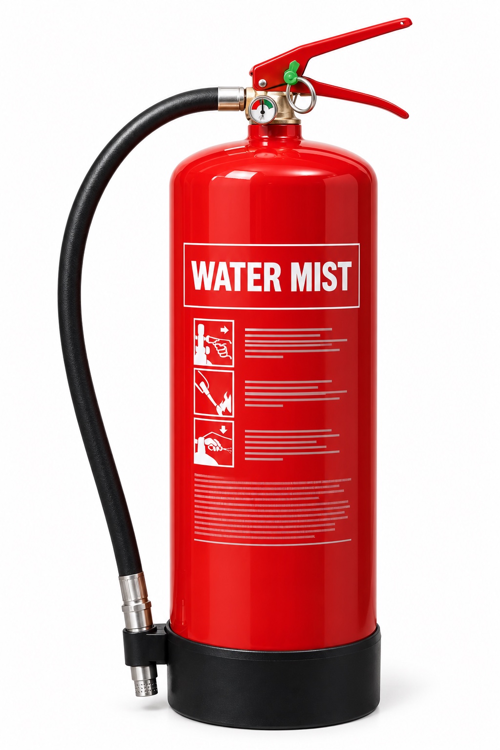
Fine-mist nozzle
The specially designed nozzle creates the intended fine spray. It is not an ordinary water jet. Nozzle appearance alone does not establish any tested electrical suitability.
Base / protective boot
The boot protects the base on this example. Other models have a different foot arrangement or no separate boot. Check the approved mounting and access rather than guessing from the picture.
Water mistManufacturer marking varies
Model-specific; commonly A, some F
Fine droplets absorb heat. Some products have additional ratings or tested electrical suitability, with stated voltage and distance conditions.
Check the limitation
‘Mist’ is not universal approval. Use only the classes and electrical conditions actually declared for that model; do not assume it covers metals, liquids or batteries.
Parts in text
Cylinder
The pressure vessel holds the agent and propellant as designed. Report corrosion, dents or other damage. Do not open, refill or repair it as an awareness check.
Agent name and colour marking
Read the actual agent name, fire ratings, electrical warnings and instructions. Colour is a recognition aid; it does not prove suitability. The illustration is not an operating label.
Fixed carrying handle
The lower fixed handle supports the unit. It is different from the upper operating lever. The exact grip and operation belong in practical instruction for the model.
Operating / squeeze lever
The upper lever operates the discharge valve when the safety device is released. Do not squeeze or discharge a unit to test it during a routine visual check.
Safety pin and pull ring
The pin mechanically prevents accidental operation. A pin or ring that is missing, distorted or insecure needs reporting; its presence does not prove the unit is serviceable.
Tamper indicator / snap-lock seal
The breakable indicator or snap-lock seal shows possible disturbance. Designs can use a separate pin-retaining strap or a pin-mounted indicator. It is different from the mechanical safety pin and is not a theft lock. Report it if broken or missing.
Pressure gauge
On this stored-pressure example the gauge indicates pressure, not the mass of agent remaining. A pointer in the marked range does not prove the cylinder is full or the unit has passed its service checks.
Hose, nozzle or applicator
The flexible hose ends in the model’s discharge nozzle. The clip is for stowage; a hose being clipped in place is not a service check. Do not block, detach or test-discharge it during a visual inspection.
Base / protective boot
The boot protects the base on this example. Other models have a different foot arrangement or no separate boot. Check the approved mounting and access rather than guessing from the picture.
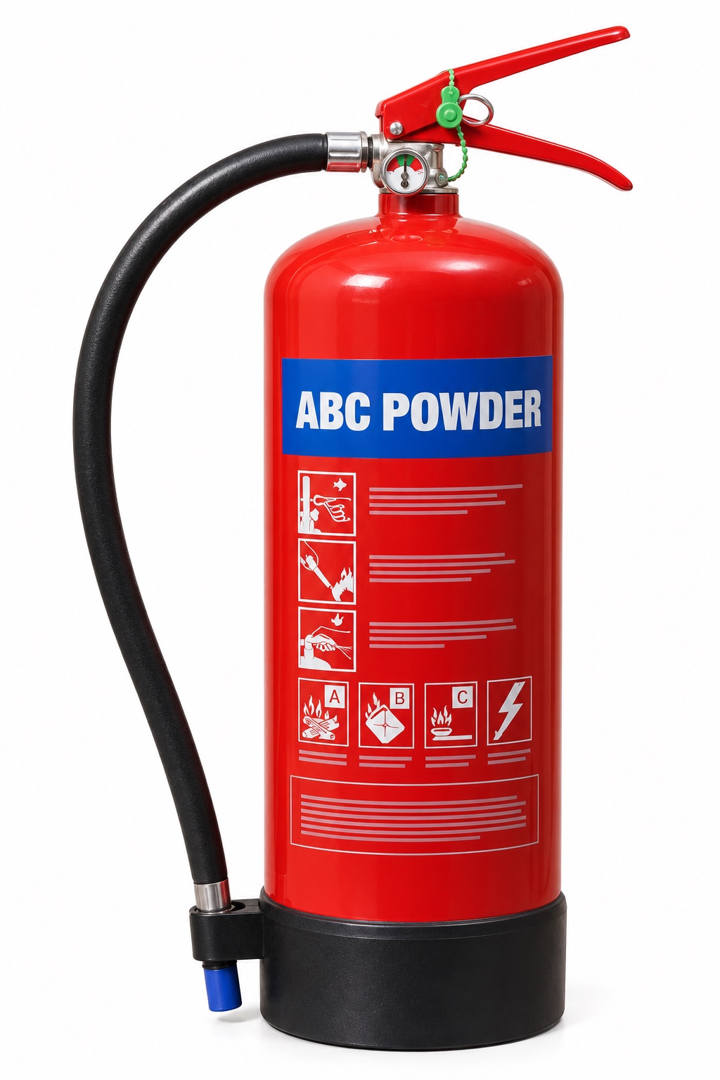
ABC dry powderBlue panel / ABC POWDER
A, B and C if marked
Interrupts flame chemistry; multipurpose powder also acts on Class A material. A C marking does not authorise tackling a gas leak.
Check the limitation
Powder can obscure escape and impair breathing; it is not generally recommended indoors. Limited cooling allows reignition. It is not metal-specific D powder or a substitute for F-rated cooking-oil equipment.
Parts in text
Cylinder
The pressure vessel holds the agent and propellant as designed. Report corrosion, dents or other damage. Do not open, refill or repair it as an awareness check.
Agent name and colour marking
Read the actual agent name, fire ratings, electrical warnings and instructions. Colour is a recognition aid; it does not prove suitability. The illustration is not an operating label.
Fixed carrying handle
The lower fixed handle supports the unit. It is different from the upper operating lever. The exact grip and operation belong in practical instruction for the model.
Operating / squeeze lever
The upper lever operates the discharge valve when the safety device is released. Do not squeeze or discharge a unit to test it during a routine visual check.
Safety pin and pull ring
The pin mechanically prevents accidental operation. A pin or ring that is missing, distorted or insecure needs reporting; its presence does not prove the unit is serviceable.
Tamper indicator / snap-lock seal
The breakable indicator or snap-lock seal shows possible disturbance. Designs can use a separate pin-retaining strap or a pin-mounted indicator. It is different from the mechanical safety pin and is not a theft lock. Report it if broken or missing.
Pressure gauge
On this stored-pressure example the gauge indicates pressure, not the mass of agent remaining. A pointer in the marked range does not prove the cylinder is full or the unit has passed its service checks.
Hose, nozzle or applicator
The flexible hose ends in the model’s discharge nozzle. The clip is for stowage; a hose being clipped in place is not a service check. Do not block, detach or test-discharge it during a visual inspection.
Base / protective boot
The boot protects the base on this example. Other models have a different foot arrangement or no separate boot. Check the approved mounting and access rather than guessing from the picture.
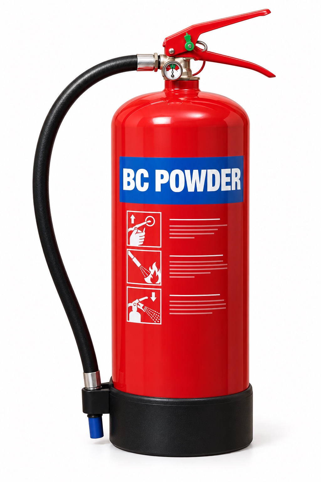
BC dry powderBlue panel / BC POWDER
B and C if marked; not A
Selected for particular liquid or gas hazards under the assessed plan. Electrical use must follow the actual unit’s instructions.
Check the limitation
Do not assume all blue powder extinguishers protect wood or paper. It has the visibility, breathing and reignition limitations of powder; it does not provide Class D or F protection.
Parts in text
Cylinder
The pressure vessel holds the agent and propellant as designed. Report corrosion, dents or other damage. Do not open, refill or repair it as an awareness check.
Agent name and colour marking
Read the actual agent name, fire ratings, electrical warnings and instructions. Colour is a recognition aid; it does not prove suitability. The illustration is not an operating label.
Fixed carrying handle
The lower fixed handle supports the unit. It is different from the upper operating lever. The exact grip and operation belong in practical instruction for the model.
Operating / squeeze lever
The upper lever operates the discharge valve when the safety device is released. Do not squeeze or discharge a unit to test it during a routine visual check.
Safety pin and pull ring
The pin mechanically prevents accidental operation. A pin or ring that is missing, distorted or insecure needs reporting; its presence does not prove the unit is serviceable.
Tamper indicator / snap-lock seal
The breakable indicator or snap-lock seal shows possible disturbance. Designs can use a separate pin-retaining strap or a pin-mounted indicator. It is different from the mechanical safety pin and is not a theft lock. Report it if broken or missing.
Pressure gauge
On this stored-pressure example the gauge indicates pressure, not the mass of agent remaining. A pointer in the marked range does not prove the cylinder is full or the unit has passed its service checks.
Specialist low-velocity applicator
The specialist applicator places the compatible metal-fire agent without unnecessarily disturbing burning material. Both agent and application method must suit the specific metal; this is not an ABC powder nozzle.
Base / protective boot
The boot protects the base on this example. Other models have a different foot arrangement or no separate boot. Check the approved mounting and access rather than guessing from the picture.
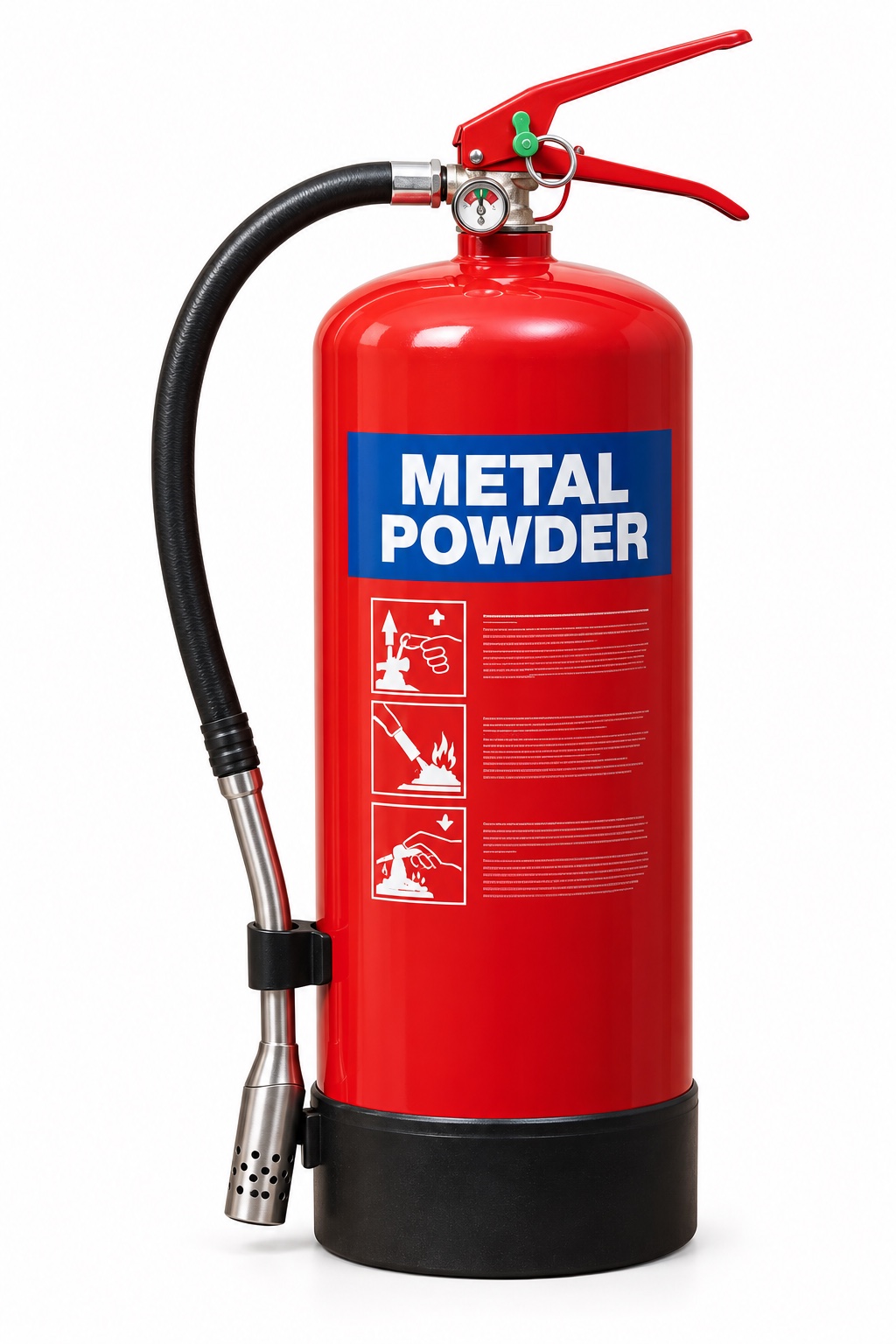
Class D specialist powderSpecific metal and agent named on label
D, for the specified metal
A specialist powder can isolate or absorb heat from a compatible burning metal. Selection requires knowledge of the metal and its form.
Check the limitation
The wrong powder can fail or react. Water, foam and CO₂ can be dangerous on certain burning metals. A powder suitable for magnesium is not automatically suitable for metallic lithium.
Parts in text
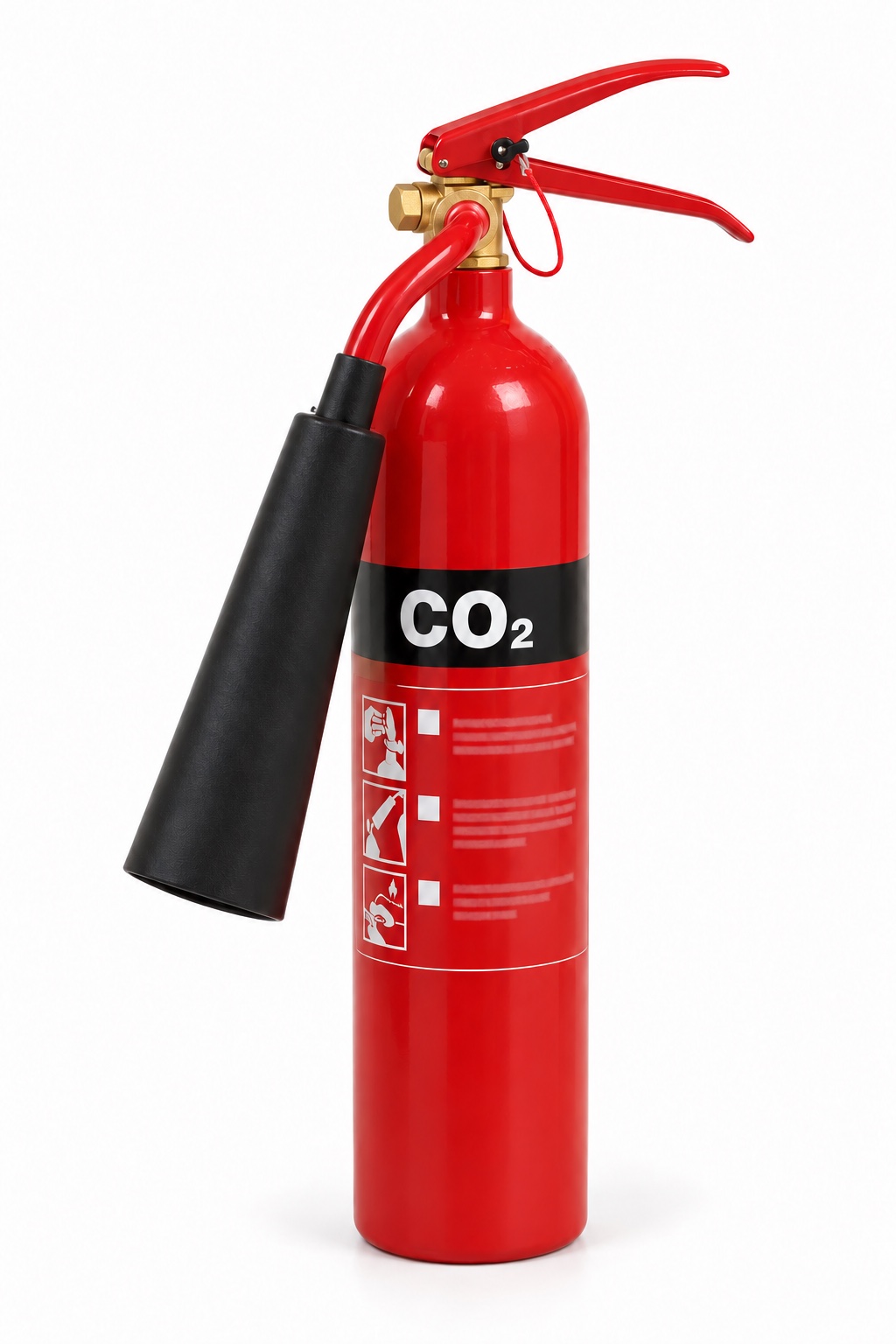
Cylinder
The narrow steel cylinder contains carbon dioxide under pressure. There is normally no pressure gauge on this portable type; service assessment includes the appropriate mass and integrity checks by competent personnel.
Agent name and colour marking
Read the actual agent name, fire ratings, electrical warnings and instructions. Colour is a recognition aid; it does not prove suitability. The illustration is not an operating label.
Fixed carrying handle
The lower fixed handle supports the unit. It is different from the upper operating lever. The exact grip and operation belong in practical instruction for the model.
Operating / squeeze lever
The upper lever operates the discharge valve when the safety device is released. Do not squeeze or discharge a unit to test it during a routine visual check.
Safety pin and pull ring
The pin mechanically prevents accidental operation. A pin or ring that is missing, distorted or insecure needs reporting; its presence does not prove the unit is serviceable.
Tamper indicator / snap-lock seal
The breakable indicator or snap-lock seal shows possible disturbance. Designs can use a separate pin-retaining strap or a pin-mounted indicator. It is different from the mechanical safety pin and is not a theft lock. Report it if broken or missing.
Horn and designated insulated grip
The flared horn directs the CO₂ discharge. Discharge parts can become extremely cold. Only the parts identified by the manufacturer as safe to hold should be gripped; not every horn is frost-free.
Displaces the atmosphere around a small flame and leaves no powder residue. Often selected around electrical equipment.
Check the limitation
Poor cooling means reignition is possible. CO₂ can create a dangerous atmosphere in enclosed spaces; discharge can cause frostbite. Hold only the designated insulated parts. Not a cooking-oil or metal-fire substitute.
Parts in text
Cylinder
The pressure vessel holds the agent and propellant as designed. Report corrosion, dents or other damage. Do not open, refill or repair it as an awareness check.
Agent name and colour marking
Read the actual agent name, fire ratings, electrical warnings and instructions. Colour is a recognition aid; it does not prove suitability. The illustration is not an operating label.
Fixed carrying handle
The lower fixed handle supports the unit. It is different from the upper operating lever. The exact grip and operation belong in practical instruction for the model.
Operating / squeeze lever
The upper lever operates the discharge valve when the safety device is released. Do not squeeze or discharge a unit to test it during a routine visual check.
Safety pin and pull ring
The pin mechanically prevents accidental operation. A pin or ring that is missing, distorted or insecure needs reporting; its presence does not prove the unit is serviceable.
Tamper indicator / snap-lock seal
The breakable indicator or snap-lock seal shows possible disturbance. Designs can use a separate pin-retaining strap or a pin-mounted indicator. It is different from the mechanical safety pin and is not a theft lock. Report it if broken or missing.
Pressure gauge
On this stored-pressure example the gauge indicates pressure, not the mass of agent remaining. A pointer in the marked range does not prove the cylinder is full or the unit has passed its service checks.
Hose, lance and spray applicator
The hose feeds the long lance and purpose-designed applicator. It helps distinguish this kitchen-fire unit from an ordinary short-nozzle extinguisher. Use requires model-specific practical training.
Base / protective boot
The boot protects the base on this example. Other models have a different foot arrangement or no separate boot. Check the approved mounting and access rather than guessing from the picture.
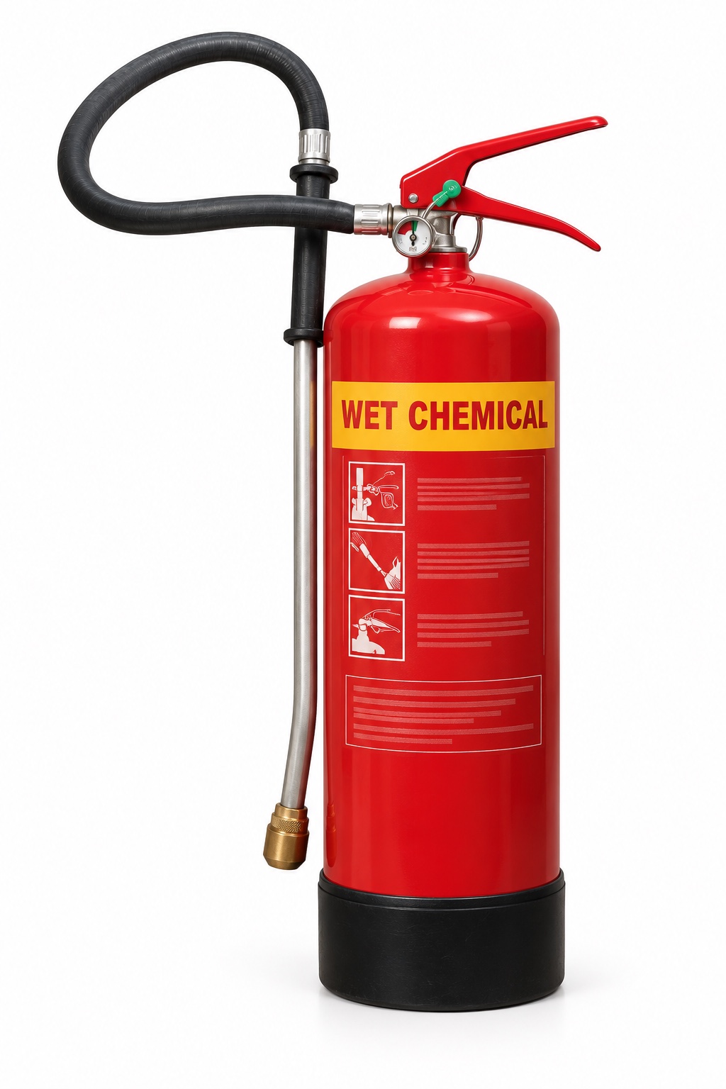
Wet chemicalYellow panel / WET CHEMICAL
F; often A if marked
Cools cooking oil and creates a protective surface layer through reaction with the fat. Use only within the actual unit’s rating and instructions.
Check the limitation
Do not mistake it for a general liquid-fire or electrical extinguisher. Incorrect application or moving the fryer can splash hot oil; apparent flame-out does not establish safe temperature.
Parts in text
Cylinder
The pressure vessel holds the agent and propellant as designed. Report corrosion, dents or other damage. Do not open, refill or repair it as an awareness check.
Agent name and colour marking
Read the actual agent name, fire ratings, electrical warnings and instructions. Colour is a recognition aid; it does not prove suitability. The illustration is not an operating label.
Fixed carrying handle
The lower fixed handle supports the unit. It is different from the upper operating lever. The exact grip and operation belong in practical instruction for the model.
Operating / squeeze lever
The upper lever operates the discharge valve when the safety device is released. Do not squeeze or discharge a unit to test it during a routine visual check.
Safety pin and pull ring
The pin mechanically prevents accidental operation. A pin or ring that is missing, distorted or insecure needs reporting; its presence does not prove the unit is serviceable.
Tamper indicator / snap-lock seal
The breakable indicator or snap-lock seal shows possible disturbance. Designs can use a separate pin-retaining strap or a pin-mounted indicator. It is different from the mechanical safety pin and is not a theft lock. Report it if broken or missing.
Pressure gauge
On this stored-pressure example the gauge indicates pressure, not the mass of agent remaining. A pointer in the marked range does not prove the cylinder is full or the unit has passed its service checks.
Hose, nozzle or applicator
The flexible hose ends in the model’s discharge nozzle. The clip is for stowage; a hose being clipped in place is not a service check. Do not block, detach or test-discharge it during a visual inspection.
Base / protective boot
The boot protects the base on this example. Other models have a different foot arrangement or no separate boot. Check the approved mounting and access rather than guessing from the picture.
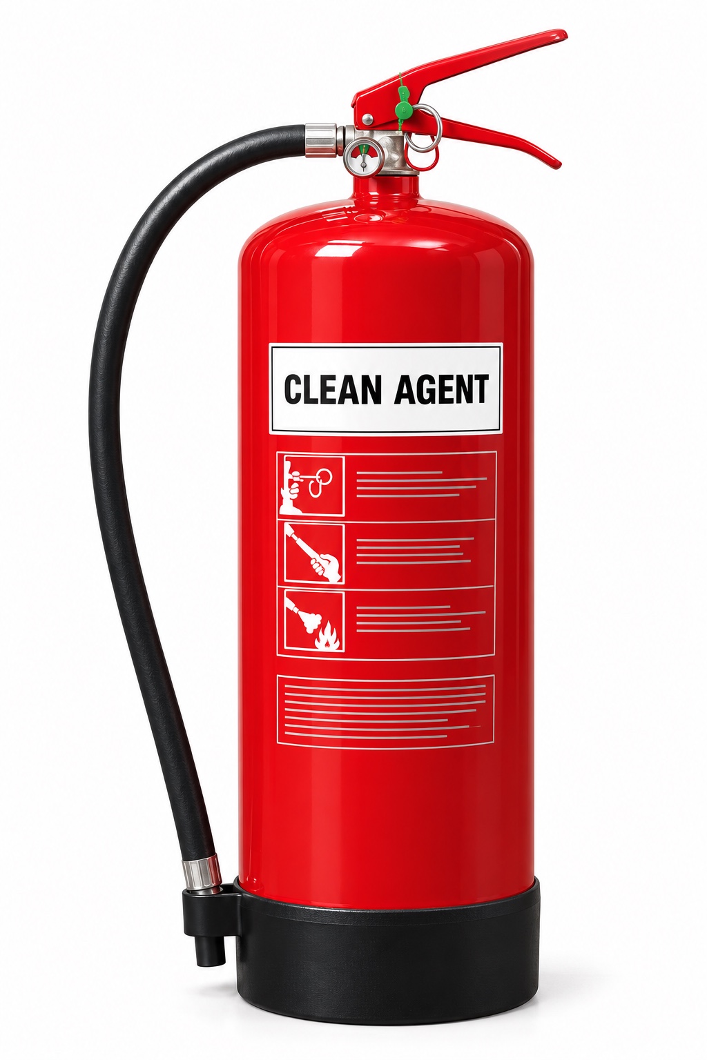
Clean agent / vaporising liquidRead the agent; no universal colour shortcut
Product- and jurisdiction-specific
Specialist low-residue agents may protect sensitive equipment. Confirm the UK-approved application and the manufacturer’s limits.
Check the limitation
Low residue does not mean safe to breathe. Do not copy a US A:B:C rating as UK gas-fire approval. Legacy halon is restricted to permitted critical uses and applicable deadlines.
Parts in text
Cylinder
The pressure vessel holds the agent and propellant as designed. Report corrosion, dents or other damage. Do not open, refill or repair it as an awareness check.
Agent name and colour marking
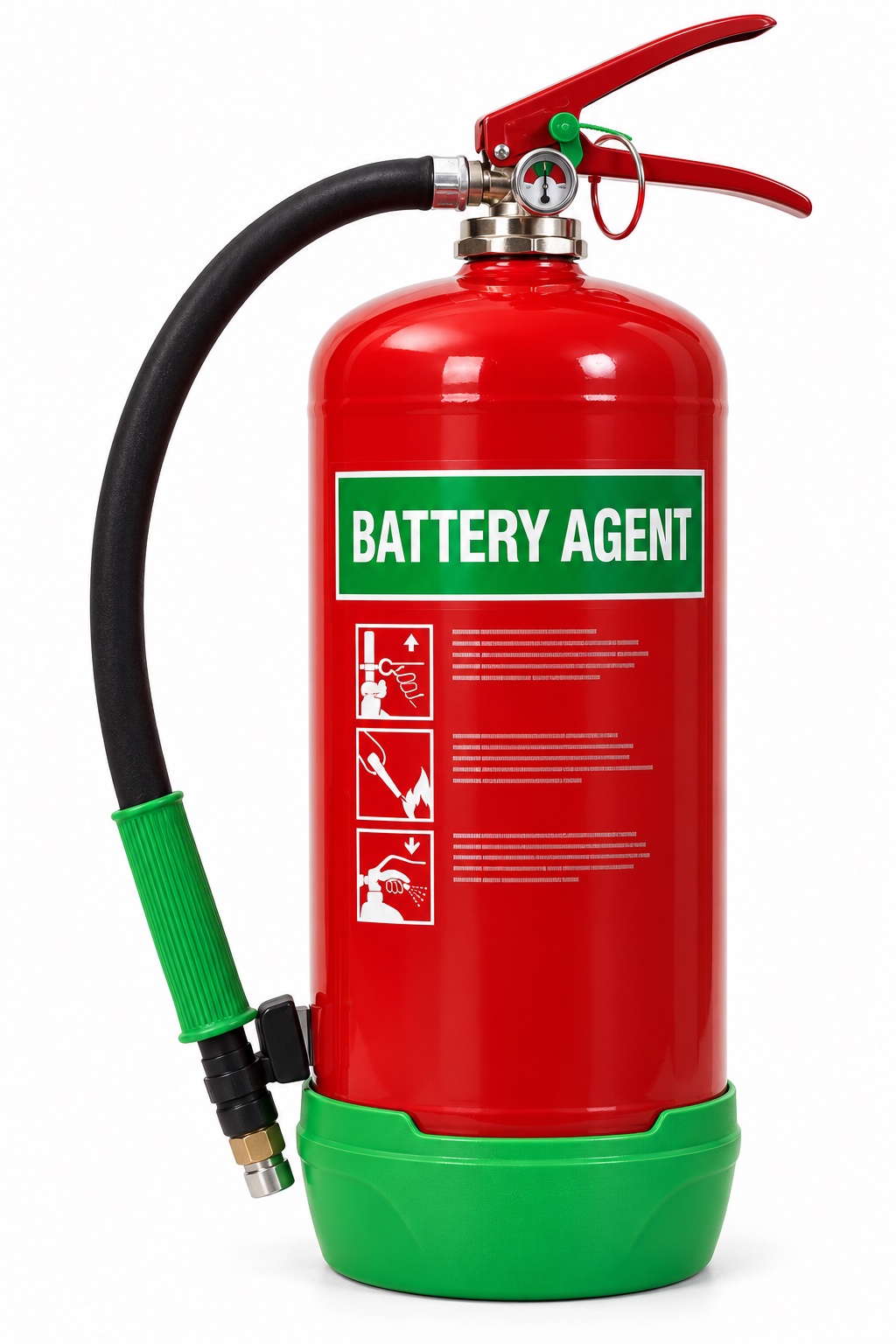
This generic illustration has a green agent area and boot inspired by the supplied product. Green is not a universal Class L identification code. Read the real product name, chemistry, battery limits and instructions.
Fixed carrying handle
The lower fixed handle supports the unit. It is different from the upper operating lever. The exact grip and operation belong in practical instruction for the model.
Operating / squeeze lever
The upper lever operates the discharge valve when the safety device is released. Do not squeeze or discharge a unit to test it during a routine visual check.
Safety pin and pull ring
The pin mechanically prevents accidental operation. A pin or ring that is missing, distorted or insecure needs reporting; its presence does not prove the unit is serviceable.
Tamper indicator / snap-lock seal
The breakable indicator or snap-lock seal shows possible disturbance. Designs can use a separate pin-retaining strap or a pin-mounted indicator. It is different from the mechanical safety pin and is not a theft lock. Report it if broken or missing.
Pressure gauge
On this stored-pressure example the gauge indicates pressure, not the mass of agent remaining. A pointer in the marked range does not prove the cylinder is full or the unit has passed its service checks.
Hose, grip and applicator
The illustrated hose has a coloured ribbed grip and a small application tip. This shows the hardware family, not a tested battery capability. Follow the instructions for the actual agent and generation.
Base / protective boot
The boot protects the base on this example. Other models have a different foot arrangement or no separate boot. Check the approved mounting and access rather than guessing from the picture.
Battery-specific suppression productsNamed formulation and tested application
Check independent scope and instructions
Some products use water-based cooling or specialist media such as aqueous vermiculite for specified battery scenarios. Selection depends on chemistry, capacity and location.
Check the limitation
A ‘lithium’ label is not proof it will stop thermal runaway in a large pack. Flame suppression may not prevent reignition or gas release. Do not approach, carry or submerge a failing battery as a learner exercise.
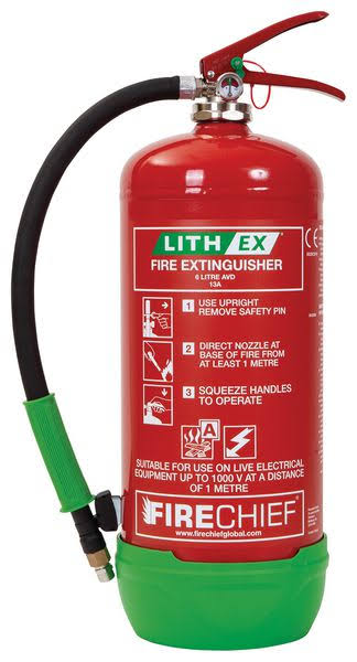
Lithium-ion product example · Firechief 6 L Lith-Ex
A named product example helps connect the generic table to an actual unit. Confirm the exact product before using its claims.
Agent and intended application
The linked Seton example uses aqueous vermiculite dispersion (AVD) for specified lithium-ion battery fire applications. Water content cools; the dispersed mineral helps form a barrier. This is not generic Class D metal-fire powder.
Read the actual rating
Seton lists a 6 L product with a 13A rating. That A rating describes its solid-material test performance; it does not, by itself, certify a universal Class L battery capability.
Match the exact model and generation
The manufacturer’s current 6 L G2 page identifies FLE6X and different discharge details from the retailer’s older listing. Do not mix their time, range or pressure values. Match the delivered label, product sheet and manual.
Check the battery scope
Confirm the allowed battery chemistry, energy capacity, state and scenario with the current manufacturer information and competent fire assessment. A large EV or energy-storage pack cannot be treated as a small-device fire.
Electrical conditions are product-specific
The supplied product label includes a voltage and minimum-distance condition. Do not transfer that condition to another battery extinguisher or infer that it makes an unsafe electrical approach acceptable.
After the flame disappears
Heat, off-gas and reignition can remain. Follow the planned withdrawal, exclusion and fire-service response; do not pick up, submerge or return a failed battery to charging.
Read the agent, fire-class letters, performance rating, electrical warnings, operating instructions and service condition. Numbers such as 13A or 55B describe standardised test performance, not a safe room size or permission to tackle that amount of fire. Colour is a clue; the actual label and assessed plan decide suitability.
What about a fire blanket?
A fire blanket is separate equipment, not an extinguisher type. It may be specified for a small contained cooking fire, but safe approach and the manufacturer’s limits still matter. Never carry a burning pan, improvise a cover or put yourself between fire and your exit.
Spot the dangerous assumption
Pause at each question, then open the explanation. These are unscored learning prompts alongside the course assessment.
A pan of cooking oil is burning. Would ordinary water help?
No. Rapid steam production can throw burning oil across the room. Raise the alarm and follow the kitchen emergency plan; never move the pan. Only a trained, authorised person should consider the specified F-rated equipment with a safe escape.
There is a C on the powder extinguisher. Should I put out the leaking gas flame?
Not as a routine response. Unburnt gas may continue escaping and form an explosive cloud. Withdraw, alarm and report the supply involved. Any safe isolation and specialist firefighting must follow the assessed emergency arrangements.
The flame around a battery has disappeared. Is the incident over?
No. Internal heat, flammable or toxic off-gas and reignition can remain. Keep clear, prevent access and tell the fire and rescue service what battery is involved. Flame-out is not permission to handle it or restart charging.
Both extinguishers have blue panels. Are the powders interchangeable?
No. Read ABC, BC or the exact Class D metal specification. Colour identifies a family; it does not establish the correct agent, rating or safe application.
A CO₂ extinguisher leaves no mess. Is it ideal in a small unventilated room?
No. A dangerous CO₂ concentration can incapacitate a person, while the fire and smoke already threaten escape. Do not enter an unsafe room. The fire plan and competent equipment selection must account for the space.
A water-mist product claims electrical suitability. Can I use any water extinguisher on a live cabinet?
No. Any tested electrical claim belongs to that particular model, with its own voltage and distance limits. It does not apply to ordinary water or another mist product, and it does not make an unsafe approach acceptable.
Source guidance and scope
UK learning context. Consult the applicable national fire guidance and your premises’ assessed plan. Manufacturer examples explain product variation; they are not product recommendations. Guidance checked 24 October 2026.
Keep steam-work and fire-agent decisions tied to their own evidence.
Control utility energy and verify the actual extinguishing medium
The separate inert training area uses a hypothetical steam-line case. It does not mean the fictional fuel terminal operates a steam plant. Steam and hot-water work can expose people to pressure and temperature after a control is switched off. For an actual system, competent people must identify sources, establish the approved isolation, safely address retained energy and prove the task-specific safe condition before intrusive work.
Pressure-system duties depend on the actual equipment and jurisdiction. Where a written scheme of examination is required, it complements rather than replaces routine maintenance and safe work control. An overdue examination is not cured by a maintenance checklist. Equally, an examination record does not authorise someone to open a hot line. Refer the real system and required competence to the responsible team.
The foam case concerns a different proof problem. A drum label does not show that the current medium, proportioning equipment, supply and delivery arrangement meet the assessed product and fire duty. Changing a medium can affect compatibility and performance; “environmentally preferable” alone cannot establish effective protection. Competent controlled change must address the actual specification, condition and suitable performance evidence, together with current legal and environmental requirements.
Firewater and extinguishing media can produce contaminated runoff requiring planned containment, recovery and disposal. Connect protection availability to these arrangements so solving the fire scenario does not ignore another route to harm. During practice, write two separate readiness statements: safe conditions for hypothetical steam maintenance and verified complete fire-agent delivery. Do not mix evidence from one into the other or offer untrained firefighting actions.
Steam, hot condensate and pressurised-air release at a valve or trap
For steam and pressurised fluids, avoid opening the system where feasible and verify pressure, temperature, trapped inventory and isolation at the work point.
The HSE links here are GB guidance used as technical reference in Northern Ireland, not a statement that GB regulations apply there. Check the actual owner instructions and NI legal route before authorising local work.
Eliminate — ERICPD Eliminate; five-level elimination. Assess whether the inspection can be made with remote temperature/condition measurement or by replacing an off-line module. The engineer verifies the measurement diagnoses the fault and the pressure-system competent person checks the applicable scheme; do not open the line to find out. See HSE: Pressure Systems Safety Regulations.
Substitute or reduce — ERICPD Reduce; five-level substitution. Where feasible, redesign a hot steam duty to a lower-temperature service or lower inventory, subject to process and hygiene requirements. The design authority checks performance and avoids introducing a new contamination or failure route. See HSE: Pressure Systems Safety Regulations.
Engineering separation — ERICPD Isolate and physical Control; five-level engineering. Fit accessible isolation, drain, vent and relief arrangements appropriate to the actual system; identify trapped pockets and prove pressure/temperature safe at the work point. A competent person verifies design and pre-use test. A leaking valve, blocked gauge or unexpected heat holds the job. See HSE: safe isolation of plant and equipment, Pressure Systems Safety Regulations (NI) 2004.
Administrative control — ERICPD Control and Discipline; five-level administrative. The supervisor sets an exclusion zone, staged depressurisation method, permit and written hand-back. Check upstream/downstream users and temporary connections during the job; a changed configuration requires revised isolation. See HSE: Pressure Systems Safety Regulations.
PPE — ERICPD PPE; five-level PPE. Task-specific heat/splash protection protects against residual contact only after verified isolation. Check coverage, compatibility, condition and replacement; it cannot withstand an uncontrolled jet or bursting pipe. See HSE managing risk using PPE.
ERICPD Discipline. Inspect and maintain valves, gauges and relief devices, retain examination records where required, and investigate pressure anomalies before restarting. The owner closes defects, not merely the paperwork. See HSE: Pressure Systems Safety Regulations.
Applied case
A hypothetical steam trap is scheduled for opening before pressure and cooling are confirmed. In a separate response-store case, a labelled foam stock has no matched delivery or compatibility evidence.
Decision and explanation
Use task-specific competent evidence for the required safe condition or protective duty before authorising reliance or work.
The questions differ, but each needs relevant competent evidence. A steam boundary must be made safe for the task; fire-agent protection must meet its assessed complete-system duty.
Look closer
Teaching graphic from the linked SHAREhub source section.01 · Read the situation
A hypothetical steam trap is scheduled for opening before pressure and cooling are confirmed. In a separate response-store case, a labelled foam stock has no matched delivery or compatibility evidence.
02 · Explain the principle
The separate inert training area uses a hypothetical steam-line case. It does not mean the fictional fuel terminal operates a steam plant. Steam and hot-water work can expose people to pressure and temperature after a control is switched off. For an actual system, competent people must identify sources, establish the approved isolation, safely address retained energy and prove the task-specific safe condition before intrusive work.
03 · Carry it into work
The questions differ, but each needs relevant competent evidence. A steam boundary must be made safe for the task; fire-agent protection must meet its assessed complete-system duty.
Lesson 5
Diesel standby: prove delivered emergency duty
A standby label promises a function; source-to-user test evidence shows whether the function is available.
Understand this fuel-industry task
This diesel unit provides a different drive arrangement from the electric fire pump. That can improve resilience to a relevant power failure, but the engine is only part of the protection. The water source, suction and discharge route, pump, starting system, fuel, cooling, exhaust, controls and distribution all need to support the required duty. A brief engine run can reveal some faults without proving that sufficient water reaches the intended users for the necessary duration.
The case has engine-start records but unresolved fuel, battery and delivered-duty questions. Treat this as a protection-availability decision for the operations that rely on it. Define the demand from the actual fire strategy and approved performance standard; do not borrow a generic flow, pressure or duration from the model. Competent tests need to demonstrate the relevant source-to-user performance safely, including credible start and supply conditions. Protect the standby arrangement from the event it is meant to survive, and consider shared valves or water sources that can defeat both the electric and diesel paths. Any outage needs explicit impairment control and restoration evidence.
Trace the initiating event and loss of control
Step
Case pathway
initiatingEvent
A fire or supply failure calls for the standby pump under conditions different from a short routine engine run.
lossOfControl
Fuel, starting, cooling, pump or water-path failure prevents delivery of the credited firewater duty.
consequences
Active protection is unavailable or insufficient, allowing a fire to escalate and exposing responders, workers and adjacent equipment.
Choose effective safeguards
Control priority
Practical application
Eliminate
Prevent the fuel release and ignition that would demand fire protection.
Substitute
Reduce escalation potential through safer inventory and layout choices.
Engineer
Provide a suitably protected and reliable supply, pumps and distribution.
Manage
Control impairments, inspect valves and test availability against performance standards.
Protect
Only trained responders use response equipment within the planned capability.
Define the required diesel-pump delivery and sustained duty from the justified site fire scenarios and users, including simultaneous demand where relevant.
Maintain and monitor the complete starting, fuel-quality and supply, cooling, exhaust, control and pump arrangement, with suitable environmental and event protection.
Use competent planned performance tests that demonstrate the required water delivery and relevant failure response, rather than engine noise or start counts alone.
Escalate unverified or failed duty through the impairment process; restrict affected operations or apply authorised alternative protection until restoration is proved.
Verify effectiveness before release
Trace the complete water route and engine dependencies against the approved performance standard, checking actual tank levels, valve positions and relevant outstanding defects.
Review representative start and delivered-duty test evidence with competent personnel, identifying which demand, duration and supply conditions it demonstrates.
Check impairment decisions reach operations and responders, and that restoration includes accepted test results and reinstated controls before availability is declared.
Transfer the decision to the workplace
Use this duty-based assurance for generators, UPS supplies and instrument-air reserves: a start or healthy indication is not proof of capacity, duration and safe failure response.
Why is firewater reliability critical?
Firewater reliability is critical because several active fire protection systems may depend on the same supply during the same emergency.
A firewater system includes more than a tank and pump. It may include water sources, suction arrangements, diesel and electric pumps, jockey pumps, pump houses, ring mains, sectional valves, hydrants, monitors, deluge valves, strainers, foam proportioners, test lines, standby power, fuel supplies and winterisation. A single closed valve, failed diesel start, blocked strainer or empty foam tank can defeat several downstream systems.
A no-flow pump start test may show that a pump starts, but not that water reaches the protected point at the required flow and pressure under credible simultaneous demand. The current design basis, manufacturer instructions and competent test plan determine what functional and flow evidence is needed. Check valves, hydrants, backup sources, alarms and known impairments as part of that assurance.
Sites also need to think about demand conflict. If sprinklers, monitors, deluge systems and emergency responders all draw from the same firewater network, the design must show that the system will not be starved during the credible scenario.
Firewater reliability checks
Firewater element
What can fail
Assurance evidence
Water source
Insufficient volume, poor replenishment, frozen supply or contaminated suction.
Tank level checks, capacity review, refill arrangements and inspection records.
Fire pumps
Failure to start, low flow, low pressure, fuel issue or maintenance defect.
Closed sectional valves, leaks, corrosion, pressure loss or poor labelling.
Valve line walks, lock/seal status, pressure tests and drawings.
Hydrants and monitors
Obstruction, damage, poor access, low pressure or poor reach.
Hydrant tests, monitor range checks, access inspections and responder drills.
Deluge and spray systems
Blocked nozzles, failed deluge valve, inadequate coverage or disabled actuation.
Functional tests, nozzle inspection, coverage checks and impairment records.
Common-cause dependencies
Power loss, flood, fire in pump house, cyber/control failure or multiple simultaneous demands.
Scenario testing, backup power checks, emergency exercises and design review.
Applied case
The diesel engine starts each week, but a battery defect is open and the last test did not establish delivery at the protected users.
Decision and explanation
Apply the approved impairment decision and demonstrate the required complete duty before relying on it.
Engine operation proves only part of the chain. Starting reliability under demand and the delivered water duty remain unresolved. This links availability to the actual fire-protection function and its dependencies, with an authorised operating decision while evidence is missing. The diesel may be credited for loss of that electrical supply or another demand. The remaining capability and restrictions require a competent review.
Look closer
Teaching graphic from the linked SHAREhub source section.01 · What to notice
The fire-pump house has a diesel standby unit. The case shows engine-start records but an unresolved fuel, starting-battery and delivered-duty review.
02 · Trace the harm
An engine can start without providing the required water flow, pressure or duration; a standby label can conceal unavailable protection.
03 · Test the safeguard
Use suitable competent performance tests and records for the complete supply-to-user system, including sustained duty and the credible failure conditions in the approved standard.
Lesson 6
Two pumps: examine independence and common causes
Ask what can fail together, not just how many items are installed. Independence belongs to a complete safety function.
Understand this fuel-industry task
The electric duty pump and diesel standby look like separate pieces of equipment. Their availability still depends on more than the prime movers. A shared water source, suction restriction, closed discharge valve, vulnerable control supply, cable route or maintenance error can defeat several functions together. Redundancy adds another item; diversity uses different arrangements to reduce relevant shared failure mechanisms. Neither automatically establishes independence for every scenario.
This exercise identifies a common power or cable dependency that was not reviewed. Trace what the initiating fire, flood, electrical fault or maintenance activity could disable, then ask whether the claimed backup remains able to start and deliver its duty. Independence includes sensing, control, final action, utilities, physical location and management of changes and tests. The competent design basis must justify availability and survivability; counting two nameplates is not an analysis. If the credited resilience cannot currently be demonstrated, make the limitation visible and control affected operations until the review and required corrective work are complete.
Trace the initiating event and loss of control
Step
Case pathway
initiatingEvent
A fire, flood, supply fault or common maintenance action challenges a shared dependency.
lossOfControl
The event disables both the normal firewater path and the protection credited as its independent backup.
consequences
The site loses mitigation during the very incident it was intended to control, increasing escalation and responder exposure.
Choose effective safeguards
Control priority
Practical application
Eliminate
Prevent the fuel release and ignition that would demand fire protection.
Substitute
Reduce escalation potential through safer inventory and layout choices.
Engineer
Provide a suitably protected and reliable supply, pumps and distribution.
Manage
Control impairments, inspect valves and test availability against performance standards.
Protect
Only trained responders use response equipment within the planned capability.
Map the complete functions and dependencies of duty and standby paths, including water, power, controls, valves, physical routes and starting arrangements.
Justify redundancy, diversity, separation and survivability against the actual credible common-cause scenarios through competent engineering assessment.
Control modifications and simultaneous maintenance so a temporary shared dependency or isolated common valve cannot silently invalidate the design assumptions.
Apply a proportionate impairment decision when independence or availability is unverified, with named restoration actions and communication to affected operations and responders.
Verify effectiveness before release
Challenge the dependency drawing with a credible single event and identify every affected element, comparing the result with the actual field installation.
Review safe loss-of-supply or alternative performance tests and supporting design evidence to establish what the backup can achieve under the credited failure condition.
Check maintenance, change and test records for common components or simultaneous unavailability, then verify the as-left system preserves the approved protection.
Transfer the decision to the workplace
At the VRU, the same principle prevents counting control and protection on one fault-sensitive system as two independent layers; at tanks, shared final valves can also matter.
Loss of cooling, instrument air or power that defeats a protective function
For a protective utility dependency, redesign away from the single failure where practicable, then test the final safe action at the actual process load.
The HSE links here are GB guidance used as technical reference in Northern Ireland, not a statement that GB regulations apply there. Check the actual owner instructions and NI legal route before authorising local work.
Eliminate — ERICPD Eliminate; five-level elimination. Remove the hazardous transfer step where feasible to eliminate that task. If the transfer remains, designing it so it cannot start when the credited cooling or air function is unavailable is engineering protection; retain the operational hold and approved safe-state response. The process design authority checks the full demand sequence and records why any remaining dependency cannot be eliminated. See HSE: reliability of utilities.
Substitution versus reduction — ERICPD Reduce; five-level substitution assessed. Test whether a less hazardous material or a different batch process could remove the need for the credited cooling or air function. Where the product or quality requirement rules that out, record why substitution is infeasible; reduce inventory or operating rate only within a hazard-reviewed envelope and confirm that the single-point failure has not moved elsewhere. See HSE: reliability of utilities.
Engineering separation — ERICPD Isolate and physical Control; five-level engineering. Provide independently routed supplies, monitored pressure/flow, fail-safe valve action and tested shutdown where the hazard study requires them. The engineer tests end-to-end response at the final load and checks common-cause paths; a generator start alone does not prove protection. See HSE: control systems technical measures, HSE: COMAH technical assessment criteria.
Administrative control — ERICPD Control and Discipline; five-level administrative. Operations restrict or stop transfer for degraded supply under a named decision threshold; the permit/change owner controls temporary connections. Confirm field state and handover every shift. An alarm bypass or unexplained pressure drift is a stop trigger. See HSE: reliability of utilities.
PPE — ERICPD PPE; five-level PPE. Task protection for residual maintenance exposure may be specified after the process is safe, but no wearable item compensates for loss of a critical protective utility. Check and replace task PPE per the actual hazard assessment. See HSE managing risk using PPE.
ERICPD Discipline. Sample end-to-end tests, trend nuisance alarms and outages, and close common-cause defects. Management checks that the stated safe state actually occurs before accepting return to service. See HSE: reliability of utilities.
Classification check: removing the hazardous transfer is elimination. Designing a start-prevention interlock when the utility is unavailable is engineering protection. Retain the approved operational hold, safe-state response and final-function testing; an inhibited start does not remove the hazard from the plant.
Applied case
A review finds that backup initiation relies on a cable route exposed to the same event that can stop the electric duty pump. Both units pass individual service checks.
Decision and explanation
Individual pump checks do not establish resilience to the shared event; review and control the common dependency.
The relevant failure condition can defeat both functions despite healthy individual machines. Independence must be demonstrated for the complete path. Diverse drives can reduce some dependencies, but water, control, route and maintenance vulnerabilities can still be shared. An indicator cannot remove a common failure path. The actual design and demonstrated duty determine what credit is justified.
Look closer
Teaching graphic from the linked SHAREhub source section.01 · What to notice
The electric duty pump and backup controls appear separate, but the exercise dependency sketch routes both through an unreviewed shared power or cable path.
02 · Trace the harm
A single fire, flood or supply fault can disable several credited barriers together; two pumps do not automatically provide independent protection.
03 · Test the safeguard
Review approved dependency analysis and suitable tests of credible supply loss, then confirm the intended backup can deliver the required function independently.
Lesson 7
Jockey pressure: distinguish a static condition from fire-demand delivery
A normal condition at low demand does not prove capacity under emergency demand. Identify the duty behind every indicator.
Understand this fuel-industry task
The small jockey pump maintains pressure and deals with the normal pressure-maintenance duty of the fire-main arrangement. The larger electric and diesel units have different defined duties for fire demand. A gauge can show normal pressure when little water is moving, even though an isolated path, unavailable main pump or restricted supply would prevent the required flow during an incident. Pressure at rest is therefore not evidence of full firewater capability.
The proposed availability check relies only on the normal gauge and the sound of the small pump. The learner should ask which duty each unit performs, how demand initiates the required main-pump action and how the water reaches protected users. The approved system standard establishes the sequence, alarms, capacity and test arrangements; no universal start settings or flow values follow from this illustration. Unexpected jockey cycling may also warrant investigation under the actual operating method, rather than repeatedly acknowledging it. Availability needs evidence for the complete demand condition, not simply confirmation that one part of the system is keeping a gauge steady.
Trace the initiating event and loss of control
Step
Case pathway
initiatingEvent
A fire creates a demand far beyond normal pressure maintenance.
lossOfControl
The team has mistaken a healthy static pressure indication and jockey operation for proof that main pumping and distribution are available.
consequences
Insufficient delivery leaves fire-protection users ineffective, increasing fire escalation and exposure of people and equipment.
Choose effective safeguards
Control priority
Practical application
Eliminate
Prevent the fuel release and ignition that would demand fire protection.
Substitute
Reduce escalation potential through safer inventory and layout choices.
Engineer
Provide a suitably protected and reliable supply, pumps and distribution.
Manage
Control impairments, inspect valves and test availability against performance standards.
Protect
Only trained responders use response equipment within the planned capability.
Identify and communicate the separate jockey, electric-duty and diesel-standby roles using the approved firewater operating and performance standard.
Maintain the required main-pump initiation, control, supply and distribution arrangements; manage their outages separately from pressure-maintenance availability.
Use suitable competent tests to demonstrate the required delivery under demand, including the relevant initiation and supply conditions.
Investigate abnormal pressure-maintenance behaviour, alarms or cycling through the site method, and make any effect on protection availability explicit.
Verify effectiveness before release
Compare pump identities and roles with current field labels, instructions and cause-and-effect; ask the operator which unit meets each demand case.
Review the evidence for main-pump start and delivered flow at relevant users, noting that a static gauge or a jockey-run test does not establish this duty.
Check the actual water route and outstanding defects, and confirm the impairment process is triggered when the required main function is unavailable or unverified.
Transfer the decision to the workplace
Apply this to a charged battery, an air receiver or a full-looking storage tank: reserve and delivered performance require evidence beyond a normal standing indication.
Why is firewater reliability critical?
Firewater reliability is critical because several active fire protection systems may depend on the same supply during the same emergency.
A firewater system includes more than a tank and pump. It may include water sources, suction arrangements, diesel and electric pumps, jockey pumps, pump houses, ring mains, sectional valves, hydrants, monitors, deluge valves, strainers, foam proportioners, test lines, standby power, fuel supplies and winterisation. A single closed valve, failed diesel start, blocked strainer or empty foam tank can defeat several downstream systems.
A no-flow pump start test may show that a pump starts, but not that water reaches the protected point at the required flow and pressure under credible simultaneous demand. The current design basis, manufacturer instructions and competent test plan determine what functional and flow evidence is needed. Check valves, hydrants, backup sources, alarms and known impairments as part of that assurance.
Sites also need to think about demand conflict. If sprinklers, monitors, deluge systems and emergency responders all draw from the same firewater network, the design must show that the system will not be starved during the credible scenario.
Firewater reliability checks
Firewater element
What can fail
Assurance evidence
Water source
Insufficient volume, poor replenishment, frozen supply or contaminated suction.
Tank level checks, capacity review, refill arrangements and inspection records.
Fire pumps
Failure to start, low flow, low pressure, fuel issue or maintenance defect.
Closed sectional valves, leaks, corrosion, pressure loss or poor labelling.
Valve line walks, lock/seal status, pressure tests and drawings.
Hydrants and monitors
Obstruction, damage, poor access, low pressure or poor reach.
Hydrant tests, monitor range checks, access inspections and responder drills.
Deluge and spray systems
Blocked nozzles, failed deluge valve, inadequate coverage or disabled actuation.
Functional tests, nozzle inspection, coverage checks and impairment records.
Common-cause dependencies
Power loss, flood, fire in pump house, cyber/control failure or multiple simultaneous demands.
Scenario testing, backup power checks, emergency exercises and design review.
Applied case
The electric main pump is under maintenance. Ring-main pressure looks normal because the jockey pump is operating, and someone proposes closing the outage record.
Decision and explanation
Keep the main-pump impairment visible and verify the remaining required protection through the approved review.
The gauge shows one condition at the present demand. It cannot establish the unavailable main pump’s duty or capacity through the distribution network. The required duty must be known and assured before demand. An incident is not an acceptable performance test. The system can retain pressure while a different essential function is impaired. Availability must be judged against the credited demand scenario.
Look closer
Teaching graphic from the linked SHAREhub source section.01 · What to notice
The small pressure-maintenance unit is labelled jockey pump. The proposed response assumes its normal ring-main pressure proves full firefighting capability.
02 · Trace the harm
Pressure maintenance is a different duty from delivering major fire demand; a healthy gauge can mask unavailable main pumps or restricted flow.
03 · Test the safeguard
Check the actual pump roles, main-pump start and delivery test evidence and water route; do not infer demanded flow from static pressure alone.
Lesson 8
An isolated fire-main section is a live protection impairment
A protection impairment follows the function it removes, not the location of the maintenance work.
Understand this fuel-industry task
A ring arrangement can provide more than one distribution path, but its protection depends on the real valve configuration and hydraulic capability. Closing a section for maintenance may affect distant hydrants, monitors or other users; the geographical distance from the work does not establish that they remain supplied. Other isolations, restrictions or demands can also change the remaining route. The current field configuration matters more than the ideal complete ring shown in a general diagram.
Here maintenance has isolated a section but loading still assumes full protection. Reconcile the outage before affected operation continues. The impairment review should identify which scenarios and users lose capability, who is informed, the justified operating restrictions or alternative arrangements and how long the condition can remain. Coordinate permits, other outages and responder access so a local maintenance task does not create an unseen site-wide weakness. Restoration is also controlled: a valve handle apparently returned to position does not prove full distribution performance, correct configuration or that temporary equipment and permits have been cleared.
Trace the initiating event and loss of control
Step
Case pathway
initiatingEvent
Maintenance isolates part of the fire-main network without communicating the affected protection.
lossOfControl
Operations and emergency plans continue to credit users whose required water path or performance is unavailable.
consequences
During a fire, responding teams may discover insufficient supply, delayed intervention and greater escalation potential.
Choose effective safeguards
Control priority
Practical application
Eliminate
Prevent the fuel release and ignition that would demand fire protection.
Substitute
Reduce escalation potential through safer inventory and layout choices.
Engineer
Provide a suitably protected and reliable supply, pumps and distribution.
Manage
Control impairments, inspect valves and test availability against performance standards.
Protect
Only trained responders use response equipment within the planned capability.
Plan the outage from current network and demand information, identifying every affected user and any interactions with other firewater impairments.
Authorise and communicate the impairment to operations, maintenance and relevant responders, with explicit limits or suitable alternative protection before affected work proceeds.
Control valve identity, securing, access and isolation boundaries through the permit and impairment systems, retaining visibility across shifts.
Restore through agreed handback, configuration checks and suitable system testing before formally removing restrictions and declaring the protection available.
Verify effectiveness before release
Trace affected and remaining flow paths using current drawings and safe field identification, including other closed valves or restrictions.
Compare the live impairment register with the permit board, loading assumptions and responder information; resolve mismatched status before accepting continued operation.
Review reinstatement and relevant function-test evidence, then confirm authorised people have updated the register and communicated restoration to everyone relying on it.
Transfer the decision to the workplace
Apply this to a shared tank ESD, gas detector outage or utility header repair: identify every relying task and maintain one agreed status through isolation and restoration.
How should fire protection impairment be controlled?
Impairment control prevents a degraded fire protection system being treated as if it were still fully available.
A fire watch or temporary extinguisher does not automatically replace automatic detection, a sprinkler supply, deluge or exposure cooling. State exactly which scenario is no longer protected, what work must stop, who accepts residual risk, how people are informed and what test will end the impairment.
Impairment means a system is unavailable, partly unavailable or below its required performance. Examples include an isolated sprinkler zone, a disabled fire alarm detector, a drained fire main, a failed pump, out-of-service hydrants, foam concentrate unavailable, blocked access or maintenance work affecting a protected area.
The danger is normalisation. A short impairment can become accepted, a temporary isolation can be forgotten, or production can continue while a safety-critical mitigative barrier is unavailable. Impairments should therefore be risk assessed, authorised, time limited, communicated and compensated by temporary measures such as fire watch, reduced inventory, stopped hot work, standby resources or temporary detection.
The decision to continue operation during impairment should be made at the right level. Where the system protects a major accident scenario, the decision may need senior technical or operational approval, not only local maintenance sign-off.
Check combined impairments. A live firewater fault, disabled detection loop, unavailable foam stock or blocked responder access may affect the same scenario together. Before extending an impairment or changing plant, inventory, occupancy or work, reassess the combined loss of protection, renew the named approval and operating limits, and tell every affected shift and responder contact. Restore each dependent function and verify the complete barrier before closing the hold.
Fire protection impairment controls
Impairment control
What good looks like
Evidence
Identification
Any unavailable or degraded fire protection system is formally identified.
Impairment log, tag, alarm isolation record or defect report.
Risk assessment
The credible fire scenario and compensating measures are reviewed before continuing work.
Impairment risk assessment and temporary control plan.
Authorisation
The right level of management accepts the temporary risk.
Approval record with expiry date and operating limits.
Communication
Operators, maintenance, security, emergency team and affected contractors know the impairment.
Shift handover, permit notes, control-room log and emergency-team briefing.
Compensating measures
Extra fire watch, reduced inventory, stopped hot work, temporary equipment or restricted operations are applied.
Temporary control records and supervision checks.
Restoration and close-out
System is reinstated, tested and formally handed back.
Test record, close-out note and update to impairment register.
Applied case
A fire-main section is isolated for repair. Loading has not been told because the work is at the other end of the terminal.
Decision and explanation
Identify affected users, declare the impairment and authorise the required restrictions or alternative arrangements.
A ring can improve resilience, but the actual configuration and demand determine what remains available. It is not proof of adequate supply under every isolation. This turns a hidden maintenance condition into an explicit safety decision and aligns the transfer task with the protection actually available. Maintenance already knows about the work. The gap is whether operations and responders are relying on a protection function that the outage has reduced.
Look closer
Teaching graphic from the linked SHAREhub source section.01 · What to notice
The case includes a fire-main section isolated for maintenance; the loading controller still assumes every monitor and hydrant is fully available.
02 · Trace the harm
A local isolation can remove protection from distant users, and an emergency plan may call for resources that cannot receive water.
03 · Test the safeguard
Trace affected flow paths in the field, verify restored valve status and suitable system function, and close the impairment only through authorised handback.
Lesson 9
Steam and condensate: a separate inert teaching case
Steam maintenance begins with controlled energy and verified internal conditions, not a touch test or an exploratory line break.
Understand this fuel-industry task
This non-operating display extends process-safety learning to a hypothetical steam service; it does not show steam heating of petrol or authorise any live steam task. In a real system, steam and hot condensate carry thermal and pressure energy. A pipe that appears cool outside may retain hot liquid or pressure internally. Opening a fitting to discover whether it is safe is itself a release of containment, with potential for severe scalding or mechanical injury.
Condensate handling, traps, drainage, supports and controlled start-up can also influence water hammer and other transient loads. The details depend on the actual plant design and operating conditions. For maintenance, identify the complete boundary, establish suitable isolation and secure it, then prove the required safe pressure and temperature by the approved method. Control safe release, connected return paths and stored pockets rather than relying on one surface observation. Where the pressure-system legal scope applies, the appropriate written scheme and competent examination arrangements are distinct from routine maintenance; both must reflect the real equipment and duty.
Trace the initiating event and loss of control
Step
Case pathway
initiatingEvent
A hypothetical steam or condensate fitting is opened before its internal condition and isolation are proved.
lossOfControl
Stored hot liquid or steam escapes, or a connected source re-pressurises the maintenance boundary.
consequences
Scalding, pressure-release injury, ejected parts or damage from an uncontrolled transient can harm the maintainer and nearby people.
Choose effective safeguards
Control priority
Practical application
Eliminate
Remove unnecessary stored energy and hazardous service dependencies.
Substitute
Use a simpler or lower-hazard service where suitable.
Engineer
Provide assessed safe states, separation and reliable backup for critical functions.
Manage
Map dependencies, inspect pressure equipment and test loss and restoration of supply.
Protect
Use task-specific protection for electrical, pressure, heat and noise exposure.
Keep this educational display inert; use real-system drawings, design information and competent authority for any actual steam work.
Plan and apply the suitable isolation for steam, hot-water and connected return sources, securing it and controlling trapped pressure and thermal energy.
Use approved depressurisation, drainage, cooling and proving methods with controlled destinations; never loosen a fitting as a test for pressure.
Maintain traps, drains and relevant protective equipment, review pressure-system scope and examination duties, and reinstate through the approved controlled sequence.
Verify effectiveness before release
For a real task, identify each possible supply and return path and verify how the isolation and proving method address trapped condensate and re-pressurisation.
Check the relevant examination scheme and report where applicable, distinguishing their scope from service records or a general inspection label.
Review the permit handback and safe restart plan, including the condition of drains, traps, supports and the required response to abnormal noise, vibration or temperature.
Transfer the decision to the workplace
The same stored-energy reasoning applies to the fuel pump and compressed-air receiver; the substance differs but stopping and looking are never complete isolation proof.
Steam, hot condensate and pressurised-air release at a valve or trap
For steam and pressurised fluids, avoid opening the system where feasible and verify pressure, temperature, trapped inventory and isolation at the work point.
The HSE links here are GB guidance used as technical reference in Northern Ireland, not a statement that GB regulations apply there. Check the actual owner instructions and NI legal route before authorising local work.
Eliminate — ERICPD Eliminate; five-level elimination. Assess whether the inspection can be made with remote temperature/condition measurement or by replacing an off-line module. The engineer verifies the measurement diagnoses the fault and the pressure-system competent person checks the applicable scheme; do not open the line to find out. See HSE: Pressure Systems Safety Regulations.
Substitute or reduce — ERICPD Reduce; five-level substitution. Where feasible, redesign a hot steam duty to a lower-temperature service or lower inventory, subject to process and hygiene requirements. The design authority checks performance and avoids introducing a new contamination or failure route. See HSE: Pressure Systems Safety Regulations.
Engineering separation — ERICPD Isolate and physical Control; five-level engineering. Fit accessible isolation, drain, vent and relief arrangements appropriate to the actual system; identify trapped pockets and prove pressure/temperature safe at the work point. A competent person verifies design and pre-use test. A leaking valve, blocked gauge or unexpected heat holds the job. See HSE: safe isolation of plant and equipment, Pressure Systems Safety Regulations (NI) 2004.
Administrative control — ERICPD Control and Discipline; five-level administrative. The supervisor sets an exclusion zone, staged depressurisation method, permit and written hand-back. Check upstream/downstream users and temporary connections during the job; a changed configuration requires revised isolation. See HSE: Pressure Systems Safety Regulations.
PPE — ERICPD PPE; five-level PPE. Task-specific heat/splash protection protects against residual contact only after verified isolation. Check coverage, compatibility, condition and replacement; it cannot withstand an uncontrolled jet or bursting pipe. See HSE managing risk using PPE.
ERICPD Discipline. Inspect and maintain valves, gauges and relief devices, retain examination records where required, and investigate pressure anomalies before restarting. The owner closes defects, not merely the paperwork. See HSE: Pressure Systems Safety Regulations.
Applied case
In the hypothetical case, a technician finds a cool outer casing and proposes opening the trap cover to check whether pressure remains.
Decision and explanation
Hold opening until the authorised isolation and approved pressure, temperature and stored-energy checks establish the required safe condition.
Surface temperature is incomplete evidence. The work needs a proved safe internal condition maintained by a suitable isolation boundary. That makes the person the release detector and can expose them before they can react. Use the designed safe-release and proving arrangements. Maintenance history does not establish the present operating or isolation state. Examination, maintenance and task-specific safe condition answer different questions.
Look closer
Teaching graphic from the linked SHAREhub source section.01 · What to notice
At the separate, non-operating training area, this hypothetical service case considers a steam line, trap and hot-water return. Maintenance is proposed without confirmed depressurisation and cooling.
02 · Trace the harm
Steam, hot water and trapped condensate can scald or release stored energy; unsuitable drainage can contribute to water hammer. This teaching model is not a claim that petrol needs steam heating.
03 · Test the safeguard
For an actual system, prove the approved isolation and safe condition, review the applicable examination scheme and demonstrate controlled reinstatement with competent people.
Lesson 10
Fire protection: prove product, system and medium compatibility
Changing an emergency resource is a safety-critical change: preserve the required duty and manage environmental consequences together.
Understand this fuel-industry task
The foam store is a resource, not proof that the terminal's assessed fire duty can be met. The selected medium must suit the product, fire scenario and application equipment. Water used for exposure cooling has a different purpose from a medium selected to control or extinguish a particular liquid fire. Inventory labels cannot establish delivery rate, usable stock, duration, proportioning or access. Those duties belong in a competent fire-protection design and response strategy for the actual facility.
A substitute foam concentrate can change performance or equipment compatibility even when described as an environmental improvement. Review the whole system through management of change: stored product, concentrate properties, water supply, proportioning equipment, application devices, testing, training and retained runoff. Current restrictions on certain persistent pollutants and waste handling also need a product- and jurisdiction-specific check; do not assume every fluorinated formulation has identical legal status or that an older stock may still be used. Testing and replacement can themselves generate contaminated waste. Plan an approved route and maintain protection through the change. The walkthrough is an assurance exercise for trained specialists and managers, not a mixing recipe or a direction for learners to attack a tank fire.
Trace the initiating event and loss of control
Step
Case pathway
initiatingEvent
A labelled foam stock or substitute concentrate is credited without demonstrating suitability for the assessed product and installed system.
lossOfControl
The required fire-protection duty is unavailable or ineffective when the system is demanded.
consequences
Fire can escalate to adjacent inventory and people, while unsuitable discharge or recovery creates additional environmental harm.
Choose effective safeguards
Control priority
Practical application
Eliminate
Prevent the fuel release and ignition that would demand fire protection.
Substitute
Reduce escalation potential through safer inventory and layout choices.
Engineer
Provide a suitably protected and reliable supply, pumps and distribution.
Manage
Control impairments, inspect valves and test availability against performance standards.
Protect
Only trained responders use response equipment within the planned capability.
Define the assessed fire-protection objective and product scenario and have competent specialists select the medium and complete application-system duty.
Verify usable stock, supply, equipment compatibility and response resources against that duty, including foreseeable impairments.
Control any product or concentrate replacement through management of change, manufacturer evidence, suitable testing and revised training.
Check current applicable pollutant restrictions and approved containment, decontamination and waste routes for the actual formulation and jurisdiction.
Verify effectiveness before release
Trace the claimed protective function from stored medium and water supply through proportioning and application to its intended target.
Inspect evidence for the actual concentrate and equipment combination, usable stock condition and required testing; challenge a label-only assurance.
Review the replacement plan and impairment controls together with runoff containment, waste arrangements and competent acceptance of readiness.
Transfer the decision to the workplace
Apply this to replacement pumps, detection equipment and extinguishers: a newer item only provides protection when its full function and interfaces are demonstrated.
What should be checked for foam and specialist suppression agents?
Foam and specialist agents must be compatible, available, deliverable and environmentally managed.
The older HSE technical page mentions halons, legacy foam types and old standards. That wording is not approval to buy or deploy those agents today. Confirm current product, legal and environmental requirements, manufacturer compatibility and disposal arrangements; never substitute foam or change the mix without competent system review.
Foam is not simply a stock item. It must be suitable for the fuel, application method, storage conditions and fire scenario. The wrong foam, degraded foam concentrate, poor proportioning, blocked delivery path or inadequate application rate can make the system ineffective. Environmental issues also matter, especially where foam or firewater runoff could contaminate drains, surface water or groundwater.
For flammable liquid storage, foam arrangements should be linked to tank and bund scenarios, escalation potential, access, responder tactics and runoff containment. Where older foam stocks are being replaced, the site should manage compatibility, disposal, training, test methods and emergency-service interface.
Foam and specialist suppression assurance checks
Check area
What to verify
Why it matters
Foam compatibility
Foam type suits the fuel, application method and fire scenario.
Wrong foam can fail to suppress vapours or seal the burning surface.
Foam quantity and condition
Sufficient concentrate is available, within its verified usable life, stored correctly and sampled where required.
Degraded or insufficient foam may fail during a prolonged incident.
Proportioning
System mixes foam concentrate and water at the intended concentration.
Incorrect proportioning can make the foam ineffective.
Delivery route
Foam pourers, monitors, lines, valves and nozzles are clear and operable.
Foam must reach the fire surface under emergency conditions.
Environmental control
Runoff containment, drainage isolation and disposal arrangements are planned.
Firefighting can create pollution if contaminated water and foam escape.
Responder interface
On-site and external responders know the foam strategy and limitations.
Avoids conflicting tactics and delays during escalation.
Applied case
A buyer offers a different concentrate described as greener. The team proposes topping up the existing tank without reviewing the installed proportioner or old contents.
Decision and explanation
A competent whole-system change review with compatibility, fire duty, environmental requirements and readiness evidence.
Those details do not establish fire performance, mixing compatibility, system delivery or current legal and waste requirements. Correct. A beneficial substitution still needs validated protective performance and controlled implementation across the system. An improvised sample does not validate the installed system or assessed fire duty and may create incompatible or regulated waste.
Look closer
Photorealistic illustrative UK workplace scene. Review checks: Setting: A planned tank transfer introduces a polar solvent to a protected bund; the outcome is to avoid assuming the existing hydrocarbon foam will work. Act: Verify the fuel identity and SDS, tank and bund scenario, foam concentrate approval, proportioner, application route, stock condition and runoff plan. Hold / review: Unknown fuel, obsolete foam approval, unverified mixing or no runoff route means no transfer on the assumption that any foam is suitable.01 · What to notice
The response store has labelled equipment. The case lacks evidence that the current extinguishing medium, proportioning system and supply meet the assessed product and fire duty.
02 · Trace the harm
Unsuitable or unavailable media and delivery can fail to control the intended event; incompatible changes can invalidate system performance and create environmental consequences.
03 · Test the safeguard
Check current specification, condition, suitable performance testing and controlled change evidence for the complete delivery system, plus contained runoff and disposal arrangements.
Lesson 11
A loading decision during three utility impairments
Integrate complete-duty evidence, shared dependencies and restoration control.
Bring the evidence together
Investigate fictional fire-pump, ring-main and foam evidence to decide whether protection is actually available to its users. Compare static pressure with delivered duty, trace shared failure paths and control maintenance impairments. A separate non-operating steam example develops energy-control awareness without implying that Crown Fuels operates a steam plant.
Consider the whole sequence of interfaces and degraded conditions. A local repair or completed permit cannot by itself show that every required barrier is available. Separate immediate protection, the competent technical resolution, the operating decision and independent verification.
Use the worked cases and the linked primary guidance to identify the missing information. State who owns the decision and what would keep the operation restricted. The fictional scene illustrates choices; it cannot establish actual process limits, emergency capability or permission to operate.
How should fire protection impairment be controlled?
Impairment control prevents a degraded fire protection system being treated as if it were still fully available.
A fire watch or temporary extinguisher does not automatically replace automatic detection, a sprinkler supply, deluge or exposure cooling. State exactly which scenario is no longer protected, what work must stop, who accepts residual risk, how people are informed and what test will end the impairment.
Impairment means a system is unavailable, partly unavailable or below its required performance. Examples include an isolated sprinkler zone, a disabled fire alarm detector, a drained fire main, a failed pump, out-of-service hydrants, foam concentrate unavailable, blocked access or maintenance work affecting a protected area.
The danger is normalisation. A short impairment can become accepted, a temporary isolation can be forgotten, or production can continue while a safety-critical mitigative barrier is unavailable. Impairments should therefore be risk assessed, authorised, time limited, communicated and compensated by temporary measures such as fire watch, reduced inventory, stopped hot work, standby resources or temporary detection.
The decision to continue operation during impairment should be made at the right level. Where the system protects a major accident scenario, the decision may need senior technical or operational approval, not only local maintenance sign-off.
Check combined impairments. A live firewater fault, disabled detection loop, unavailable foam stock or blocked responder access may affect the same scenario together. Before extending an impairment or changing plant, inventory, occupancy or work, reassess the combined loss of protection, renew the named approval and operating limits, and tell every affected shift and responder contact. Restore each dependent function and verify the complete barrier before closing the hold.
Fire protection impairment controls
Impairment control
What good looks like
Evidence
Identification
Any unavailable or degraded fire protection system is formally identified.
Impairment log, tag, alarm isolation record or defect report.
Risk assessment
The credible fire scenario and compensating measures are reviewed before continuing work.
Impairment risk assessment and temporary control plan.
Authorisation
The right level of management accepts the temporary risk.
Approval record with expiry date and operating limits.
Communication
Operators, maintenance, security, emergency team and affected contractors know the impairment.
Shift handover, permit notes, control-room log and emergency-team briefing.
Compensating measures
Extra fire watch, reduced inventory, stopped hot work, temporary equipment or restricted operations are applied.
Temporary control records and supervision checks.
Restoration and close-out
System is reinstated, tested and formally handed back.
Test record, close-out note and update to impairment register.
Applied case
A pump-house maintenance day leaves a ring-main section isolated. The diesel engine starts, but sustained delivery evidence is missing; electric backup controls share a vulnerable supply. A recently changed foam medium has not been matched to the proportioning system. Dispatch asks whether loading can continue. Identify affected users, competent decision owners, the authorised impairment route and the evidence required before normal availability can be claimed.
Decision and explanation
Treat the complete duty as unverified and apply the authorised impairment decision and operating limits until suitable evidence supports restoration.
Several partial observations do not establish the combined required duty. Control the actual impaired configuration and require suitable complete-system and change evidence before restoring normal reliance.
Look closer
Teaching graphic from the linked SHAREhub source section.01 · Read the situation
A pump-house maintenance day leaves a ring-main section isolated. The diesel engine starts, but sustained delivery evidence is missing; electric backup controls share a vulnerable supply. A recently changed foam medium has not been matched to the proportioning system. Dispatch asks whether loading can continue. Identify affected users, competent decision owners, the authorised impairment route and the evidence required before normal availability can be claimed.
02 · Explain the principle
Investigate fictional fire-pump, ring-main and foam evidence to decide whether protection is actually available to its users. Compare static pressure with delivered duty, trace shared failure paths and control maintenance impairments. A separate non-operating steam example develops energy-control awareness without implying that Crown Fuels operates a steam plant.
03 · Carry it into work
Several partial observations do not establish the combined required duty. Control the actual impaired configuration and require suitable complete-system and change evidence before restoring normal reliance.
Lesson 12
Turn the learning into a verified workplace action
Choose a bounded action, owner, task-specific evidence and escalation trigger within your role.
Make the course useful at work
Terminal utilities and fire protection; steam case is hypothetical and firewater/foam duty cannot be inferred from a model or product label.
Choose one relevant task from this course. Describe the material, equipment, people and interfaces, then explain the credible harm pathway before choosing the control. Follow the actual site process for obtaining missing technical evidence and deciding whether work may proceed.
Use the linked resource with a specific question. A briefing should test understanding; a checklist should identify missing facts; an audit should compare claims with observations. Keep this exercise fictional and separate from live operating records.
Record the planned action, responsible role, verification evidence and a trigger for escalation or reassessment. Completion of this course is a learning record, not an operating instruction, engineering design, specialist licence or authority to enter, isolate or fight a fire.
How should active fire protection be inspected, tested and maintained?
Inspection and testing should prove the system remains capable of meeting its design duty.
Set inspection and test intervals from the current system standard, design and manufacturer instructions, risk assessment and any applicable approval or insurance conditions. This page sets no weekly pump-test rule or universal certificate period. Distinguish a pump start result from evidence of required flow, pressure, duration and simultaneous demand.
Testing should be more than a calendar habit. It should test the safety-critical function that matters. For a pump, that may include starting reliability and flow/pressure performance. For a deluge system, it may include actuation, valve operation, nozzle condition and water distribution. For detection, it may include coverage, alarm transmission, cause-and-effect logic and response actions.
Records should be useful to decision-makers. A pass/fail tick is weaker than a record showing the test condition, result, standard, deficiency, risk significance, action owner and verification. Overdue tests, repeated faults and temporary repairs should be visible to leaders who can resource correction.
Testing itself can create risk. Wet tests, foam tests, detector isolations, alarm testing, pump tests and system drain-down can affect operations, people and the environment. The work should be planned, communicated and restored properly.
Testing devices without checking the required response or cause-and-effect.
Fire pump test
Pumps start reliably and deliver required flow and pressure.
Only proving the pump turns over, not that it meets demand.
Deluge or sprinkler inspection
Valves, nozzles, heads, pipework and coverage remain available.
Blocked nozzles, closed valves, corrosion or storage changes overlooked.
Foam system test
Foam concentrate, proportioning, delivery path and stock level remain suitable.
Foam age, compatibility or proportioning not checked.
Hydrant and monitor test
Access, pressure, flow, reach and operability are adequate.
Hydrants obstructed or monitors cannot reach credible targets.
Emergency exercise
People can interpret alarms, command response, operate systems and coordinate with external responders.
Drills only test evacuation and miss firewater, foam and impairment assumptions.
Applied case
Your handover action says improve fuel safety but names no operation, control owner, evidence or stopping condition.
Decision and explanation
Name the actual task, competent control owner, evidence required and the hold/escalation trigger.
An effective plan connects a real task and control with a responsible role, objective evidence and a clear decision boundary. A course badge or signature does not establish the plant condition.
Look closer
Teaching graphic from the linked SHAREhub source section.01 · Read the situation
Your handover action says improve fuel safety but names no operation, control owner, evidence or stopping condition.
02 · Explain the principle
Terminal utilities and fire protection; steam case is hypothetical and firewater/foam duty cannot be inferred from a model or product label.
03 · Carry it into work
An effective plan connects a real task and control with a responsible role, objective evidence and a clear decision boundary. A course badge or signature does not establish the plant condition.
Example emergency response plan
Study a completed fictional industrial construction and commissioning plan. Compare its warning, roles, accountability, responder access, rescue limits and recovery decisions with the learning above. It includes a new fictional site schematic, a worked exercise and separate blank recording annexes.
Use this as a teaching example when developing arrangements for your own premises. The fictional layout and role identifiers are not live emergency instructions.

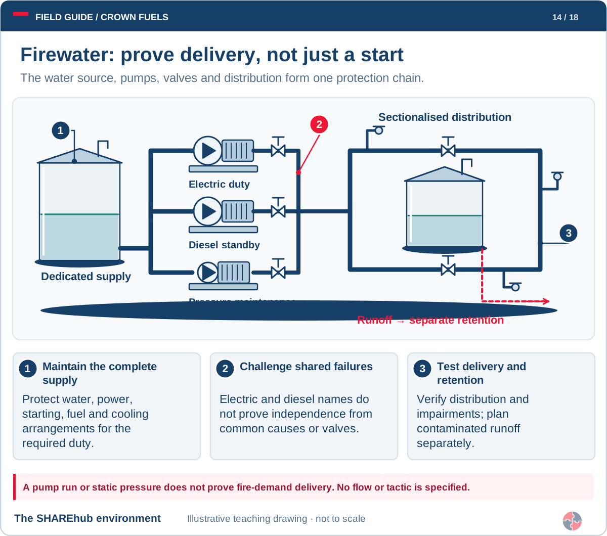
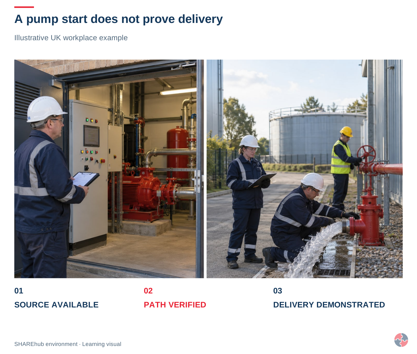
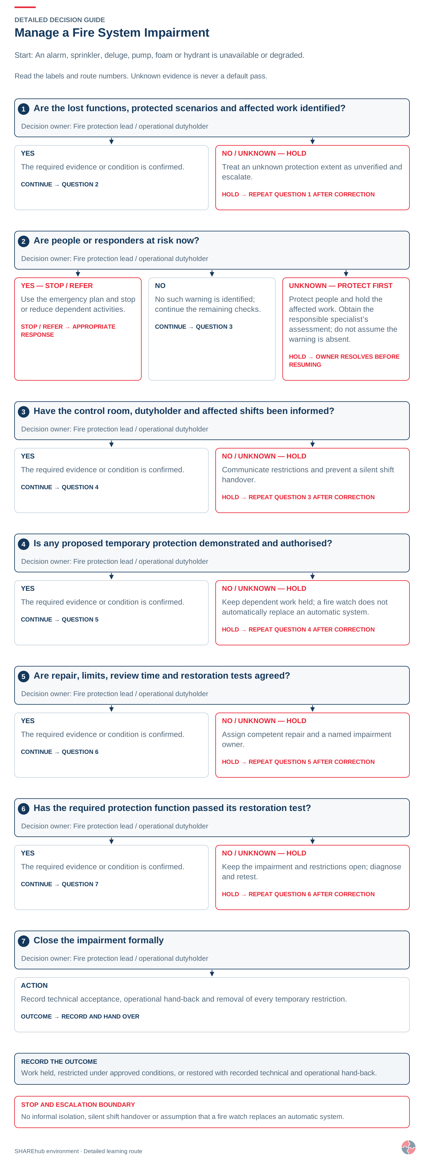
 Recognise the fuel. Read the extinguisher. Protect your escape.