Independent SHAREhub process-safety awareness using fictional cases and a Great Britain baseline; check the applicable Northern Ireland duties and actual site arrangements. This course does not award a NEBOSH qualification, establish specialist competence or authorise hazardous work.
This reader supplies the complete teaching. Use the interactive LMS course for assessed activities, saved progress and completion.
LESSON 1
Define the fire-protection duty before counting equipment
Fire classes and fire extinguishersFire classes · agent types · dangerous mismatches
Recognise the fuel. Read the extinguisher. Protect your escape.
People and escape first. Raise the alarm, follow the site’s evacuation plan and arrange the emergency call to 999. Only consider a small fire in its earliest stage if you are trained, authorised, have the correct equipment and a clear escape behind you. Smoke, spreading fire, uncertainty or an unsafe approach mean withdraw. Never delay escape to fetch an extinguisher.
UK awareness reference for common and specialist portable extinguisher families. Actual ratings, exclusions and manufacturer instructions govern each unit. Reading this guide is not practical training or permission to fight a fire. Fixed systems, hose reels and specialist industrial firefighting require their own assessed arrangements.
Process fire protection: distinguish a small first-response appliance from the engineered protection required for a major process event.
Fire classes: fuel, examples and the important distinction
Class
Fuel and examples
What matters
AClass A
Solid materials
Wood, paper, textiles and many solid plastics.
Usually forms an ember or char bed. Cooling matters; check the marked A rating.
BClass B
Flammable liquids
Petrol, solvents, diesel when burning, and liquefiable solids such as wax.
Fuel can spread across a surface. An unsuitable jet can spread burning liquid; solvent compatibility matters.
CClass C
Flammable gases
Propane, butane or methane.
Not a routine employee firefighting task. Knocking down flame while gas continues to escape can create an explosive cloud. Fuel isolation requires safe, competent action under the emergency plan.
DClass D
Combustible metals
Magnesium, sodium or metallic lithium.
Needs a metal-specific specialist agent. Ordinary ABC powder is not Class D powder.
FClass F
Cooking oils and fats
Hot oil in a fryer or pan.
Very hot oil can reignite. Water can produce violent steam expansion and eject burning oil.
LClass L
Lithium-ion batteries
A lithium-ion tool, e-bike or vehicle battery in thermal runaway.
Class L is included in BS ISO 3941:2026. Toxic or flammable gas, heat propagation and reignition need specialist planning. This is different from a metallic-lithium Class D fire.
Electrical equipment: Energised electrical equipment is an additional hazard, not a UK fire class called E. Do not import US Class C electrical or Class K cooking labels into this UK guide. Isolation, only where safe and authorised, does not remove the burning fuel or stored battery energy. Use the unit’s explicit electrical suitability and limitations.
Class L is the 2026 addition to the classification standard. Existing extinguisher labels and product test claims vary; a new class name does not certify every battery product.
Compare the classes · including lithium-ion batteries
Typical = usual application for the labelled family. If rated / unit limits = confirm the actual label and manufacturer conditions. No = not a normal selection for that hazard; specialist engineered arrangements are separate. This table cannot authorise firefighting.
* Electrical is an additional hazard, not a fire class. Gas-fire and battery-fire response require the assessed specialist plan. Scroll the table sideways on a narrow screen.
Typical portable-agent applications: always confirm the actual unit
Agent family
A · solids
B · liquids
C · gases
D · metals
Electrical*
F · cooking oil
L · Li-ion
Water
Typical
No
No
No
Unit limits
No
No
Water spray / water with additives
Typical
If rated
No
No
Unit limits
No
No
Foam
Typical
Typical
No
No
Unit limits
No
No
Water mist
Typical
If rated
No
No
Unit limits
If rated
Specialist plan
ABC dry powder
Typical
Typical
Specialist plan
No
Unit limits
No
No
BC dry powder
No
Typical
Specialist plan
No
Unit limits
No
No
Class D specialist powder
No
No
No
Exact metal
No
No
No
Carbon dioxide (CO₂)
No
Typical
No
No
Unit limits
No
No
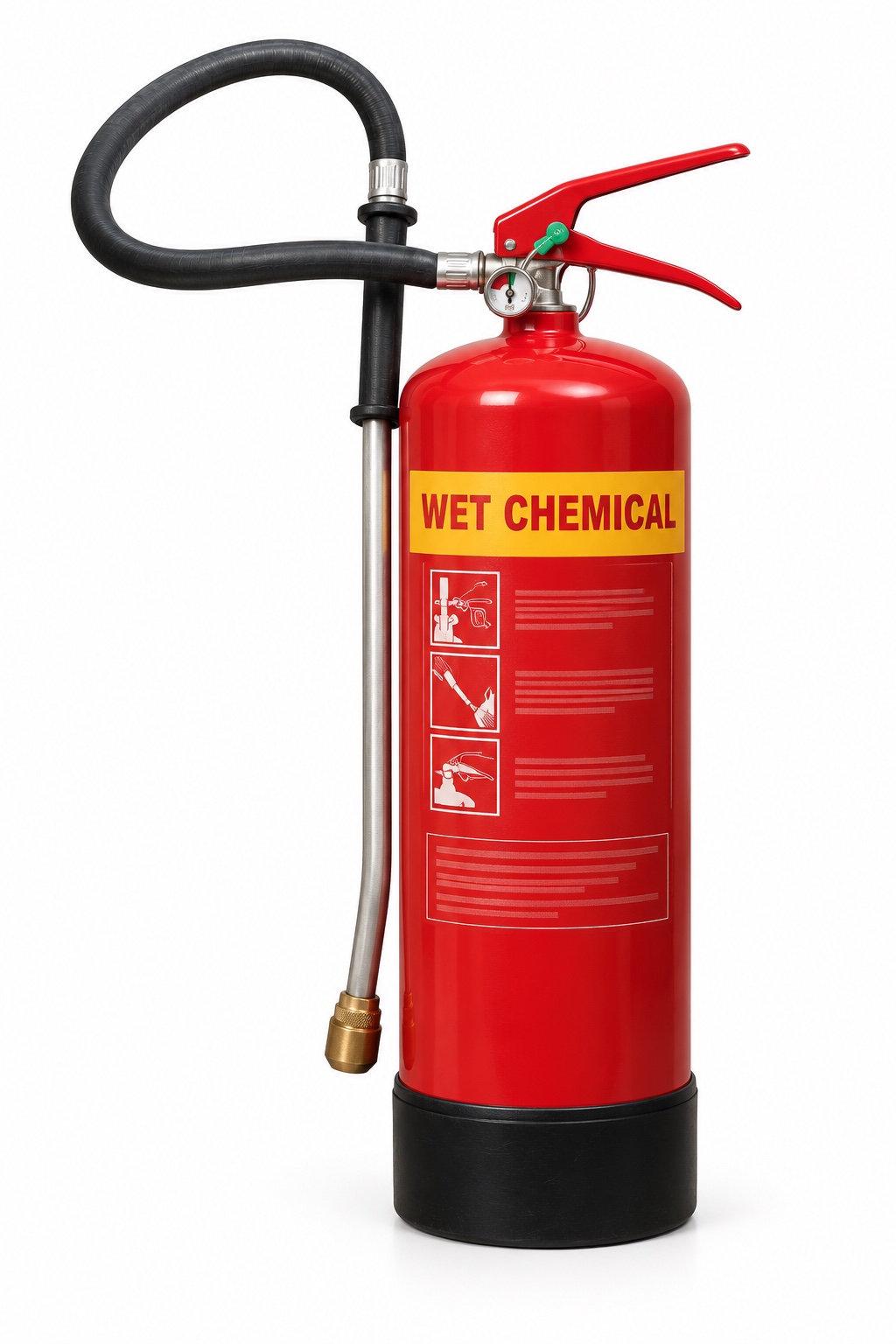
Wet chemical
If rated
If rated
No
No
Unit limits
Typical
No
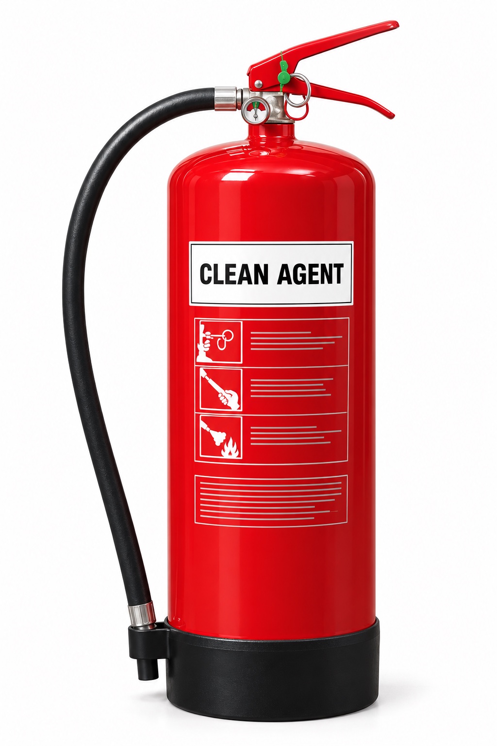
Clean agent / vaporising liquid
Unit rating
Unit rating
No
No
Unit limits
No
No
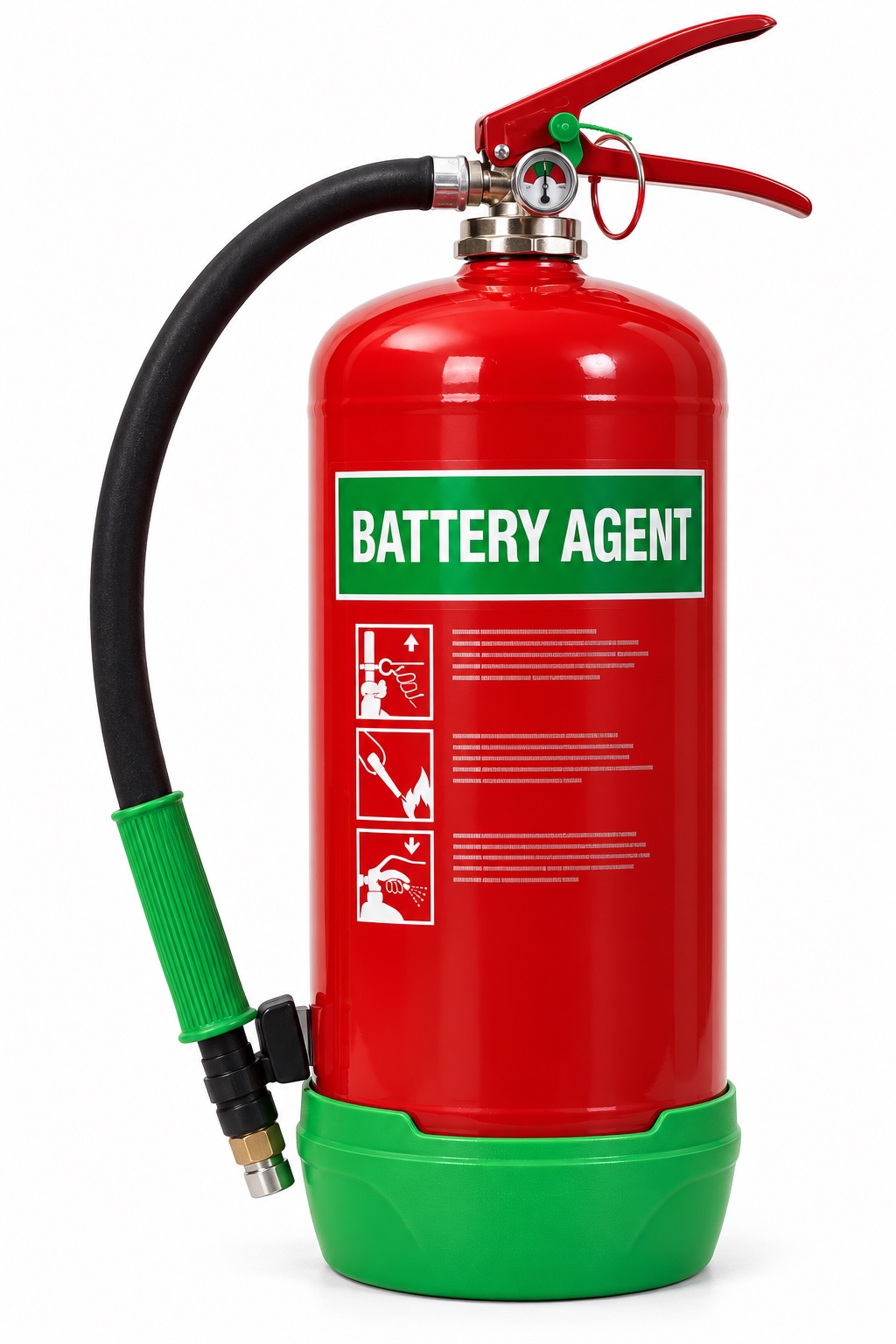
Battery-specific suppression products
If rated
No
No
No
Unit limits
No
Specified battery
Extinguisher types: uses and dangers
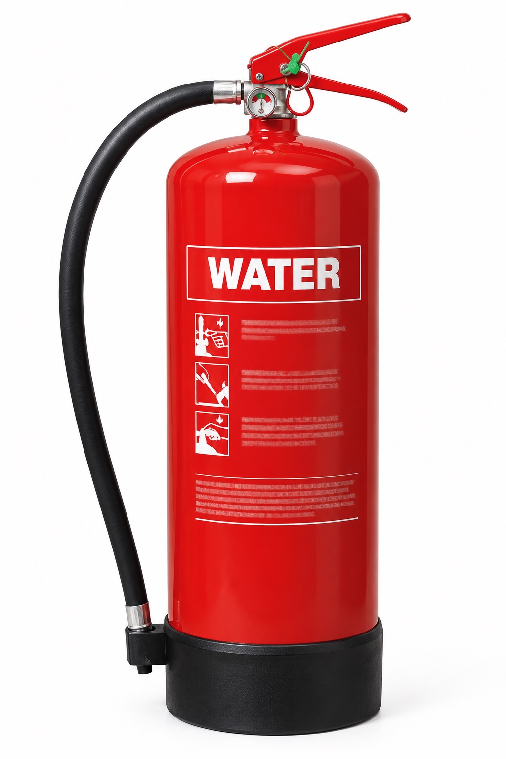
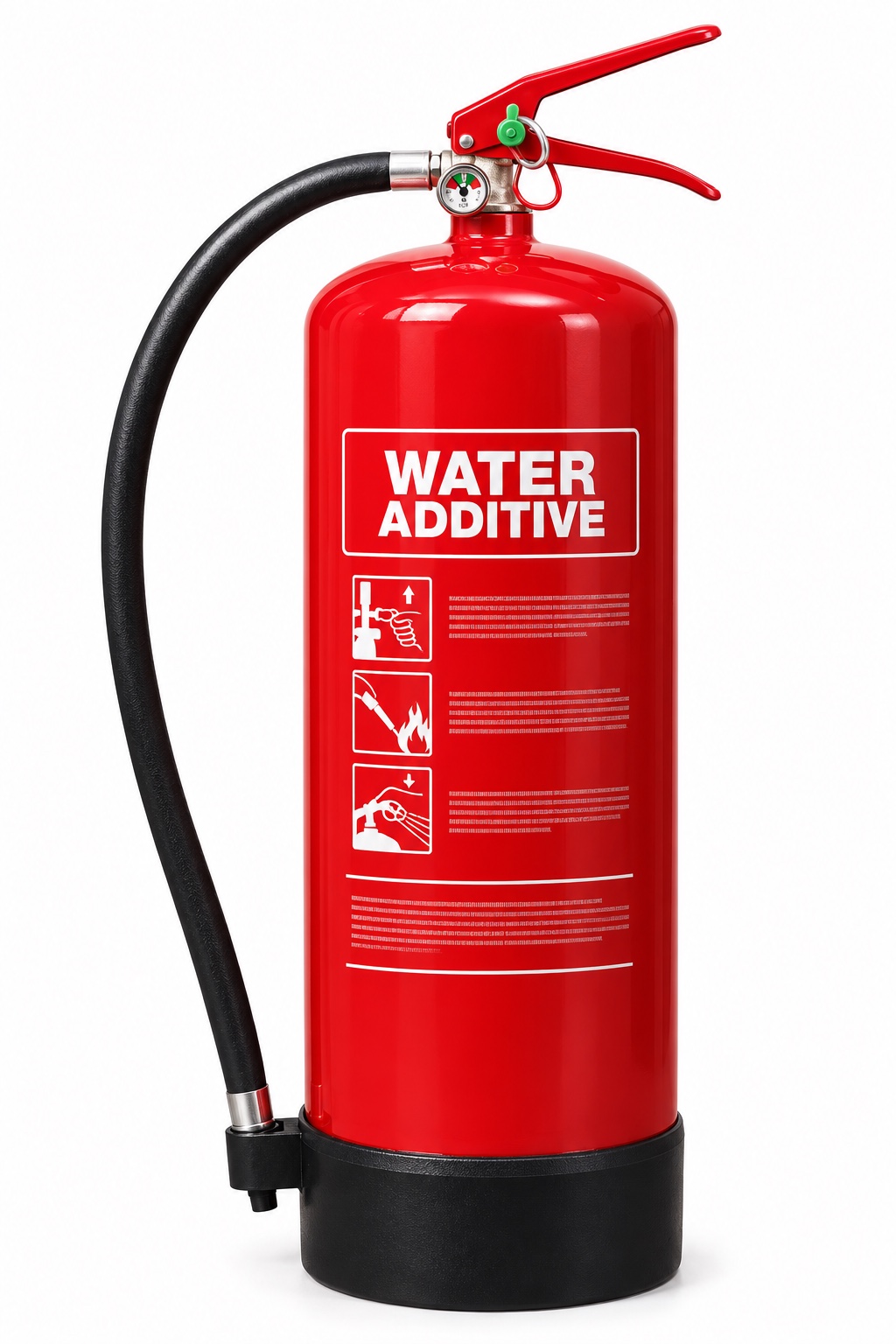
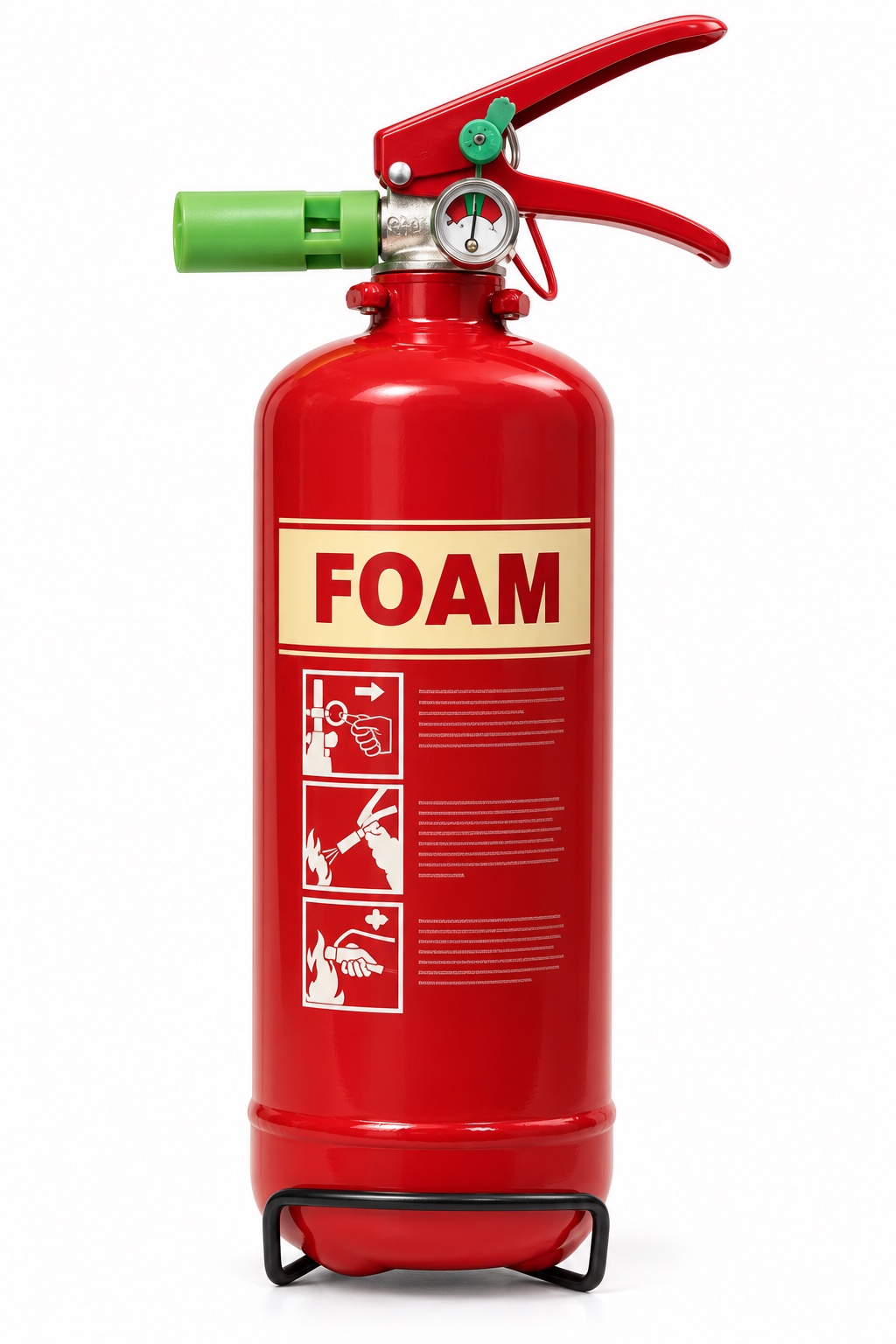
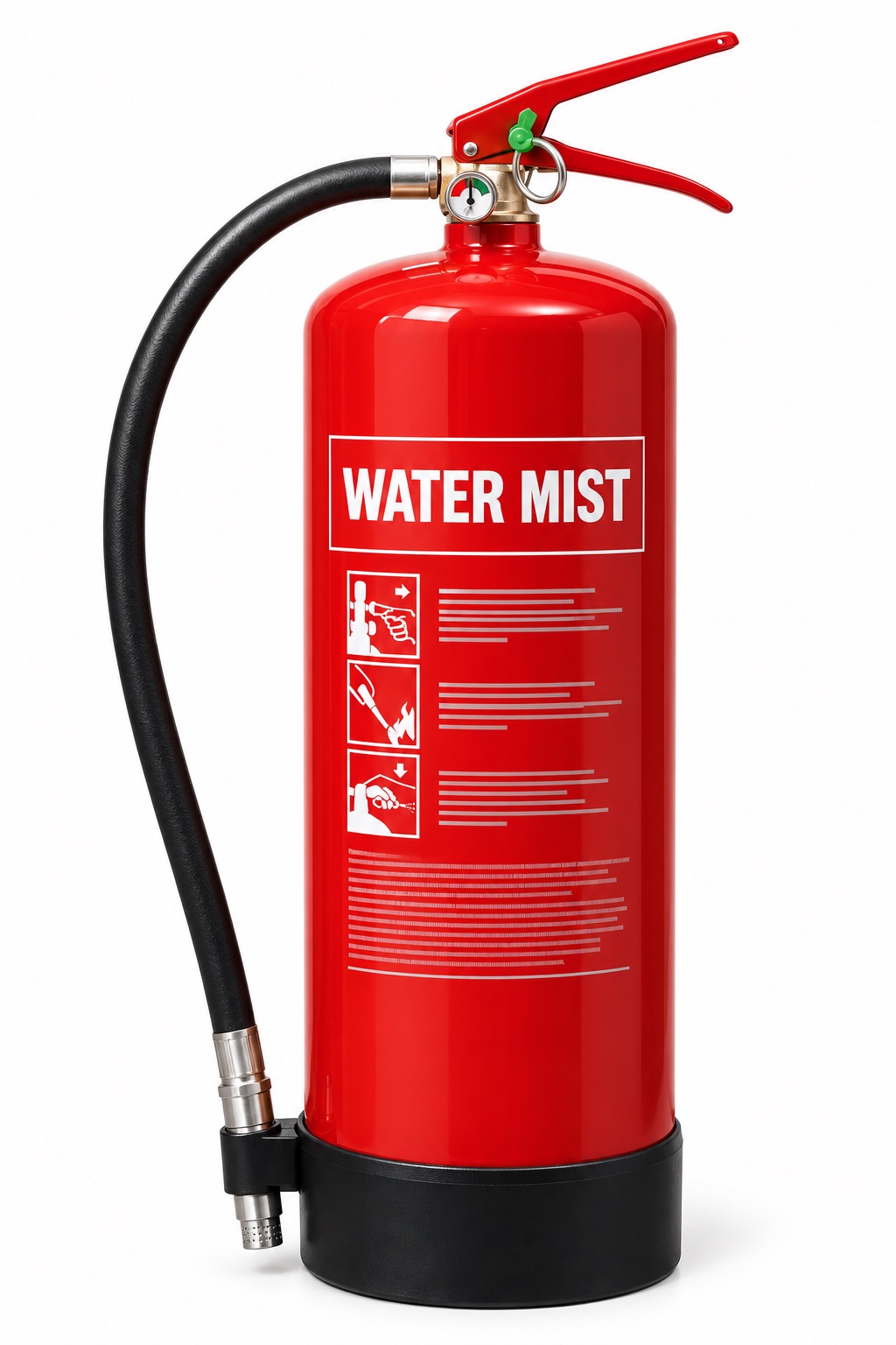
These are typical applications, not universal permissions. Check the label on the actual unit. Images are photorealistic teaching illustrations inspired by the referenced equipment; they are not photographs or certified product labels. Use Inspect the parts to explore the hardware. Band, nozzle and label details vary.
Common and specialist portable extinguisher families
Type and recognition
Typical rating and use
Wrong use: what can go wrong?
Parts in text
Cylinder
The pressure vessel holds the agent and propellant as designed. Report corrosion, dents or other damage. Do not open, refill or repair it as an awareness check.
Agent name and colour marking
Read the actual agent name, fire ratings, electrical warnings and instructions. Colour is a recognition aid; it does not prove suitability. The illustration is not an operating label.
Fixed carrying handle
The lower fixed handle supports the unit. It is different from the upper operating lever. The exact grip and operation belong in practical instruction for the model.
Operating / squeeze lever
The upper lever operates the discharge valve when the safety device is released. Do not squeeze or discharge a unit to test it during a routine visual check.
Safety pin and pull ring
The pin mechanically prevents accidental operation. A pin or ring that is missing, distorted or insecure needs reporting; its presence does not prove the unit is serviceable.
Tamper indicator / snap-lock seal
The breakable indicator or snap-lock seal shows possible disturbance. Designs can use a separate pin-retaining strap or a pin-mounted indicator. It is different from the mechanical safety pin and is not a theft lock. Report it if broken or missing.
Pressure gauge
On this stored-pressure example the gauge indicates pressure, not the mass of agent remaining. A pointer in the marked range does not prove the cylinder is full or the unit has passed its service checks.
Hose, nozzle or applicator
The flexible hose ends in the model’s discharge nozzle. The clip is for stowage; a hose being clipped in place is not a service check. Do not block, detach or test-discharge it during a visual inspection.
Base / protective boot
The boot protects the base on this example. Other models have a different foot arrangement or no separate boot. Check the approved mounting and access rather than guessing from the picture.
WaterRed / WATER marking
Normally A
Cools burning solid material such as paper, wood or fabric.
Check the limitation
Ordinary water is unsuitable for live electrical equipment, flammable-liquid pools, cooking oil and reactive metals: shock, spreading fuel or violent reaction can result.
Parts in text
Cylinder
The pressure vessel holds the agent and propellant as designed. Report corrosion, dents or other damage. Do not open, refill or repair it as an awareness check.
Agent name and colour marking
Read the actual agent name, fire ratings, electrical warnings and instructions. Colour is a recognition aid; it does not prove suitability. The illustration is not an operating label.
Fixed carrying handle
The lower fixed handle supports the unit. It is different from the upper operating lever. The exact grip and operation belong in practical instruction for the model.
Operating / squeeze lever
The upper lever operates the discharge valve when the safety device is released. Do not squeeze or discharge a unit to test it during a routine visual check.
Safety pin and pull ring
The pin mechanically prevents accidental operation. A pin or ring that is missing, distorted or insecure needs reporting; its presence does not prove the unit is serviceable.
Tamper indicator / snap-lock seal
The breakable indicator or snap-lock seal shows possible disturbance. Designs can use a separate pin-retaining strap or a pin-mounted indicator. It is different from the mechanical safety pin and is not a theft lock. Report it if broken or missing.
Pressure gauge
On this stored-pressure example the gauge indicates pressure, not the mass of agent remaining. A pointer in the marked range does not prove the cylinder is full or the unit has passed its service checks.
Hose, nozzle or applicator
The flexible hose ends in the model’s discharge nozzle. The clip is for stowage; a hose being clipped in place is not a service check. Do not block, detach or test-discharge it during a visual inspection.
Base / protective boot
The boot protects the base on this example. Other models have a different foot arrangement or no separate boot. Check the approved mounting and access rather than guessing from the picture.
Water spray / water with additivesUsually red; read the agent name
A; B only if explicitly rated
Improved wetting or spray performance can help on the hazards stated on that model’s label.
Check the limitation
An additive does not make every water extinguisher safe for electricity, oils or reactive chemicals. Check the specific exclusions.
Parts in text
Cylinder
The pressure vessel holds the agent and propellant as designed. Report corrosion, dents or other damage. Do not open, refill or repair it as an awareness check.
Agent name and colour marking
Read the actual agent name, fire ratings, electrical warnings and instructions. Colour is a recognition aid; it does not prove suitability. The illustration is not an operating label.
Fixed carrying handle
The lower fixed handle supports the unit. It is different from the upper operating lever. The exact grip and operation belong in practical instruction for the model.
Operating / squeeze lever
The upper lever operates the discharge valve when the safety device is released. Do not squeeze or discharge a unit to test it during a routine visual check.
Safety pin and pull ring
The pin mechanically prevents accidental operation. A pin or ring that is missing, distorted or insecure needs reporting; its presence does not prove the unit is serviceable.
Tamper indicator / snap-lock seal
The breakable indicator or snap-lock seal shows possible disturbance. Designs can use a separate pin-retaining strap or a pin-mounted indicator. It is different from the mechanical safety pin and is not a theft lock. Report it if broken or missing.
Pressure gauge
On this stored-pressure example the gauge indicates pressure, not the mass of agent remaining. A pointer in the marked range does not prove the cylinder is full or the unit has passed its service checks.
Direct spray nozzle
This compact foam example has a nozzle attached directly to the valve. Larger units may have a hose. Recognise the actual discharge arrangement and use only the approved agent and instructions.
Base / protective boot
The boot protects the base on this example. Other models have a different foot arrangement or no separate boot. Check the approved mounting and access rather than guessing from the picture.
FoamCream panel / FOAM
Commonly A and B
Cools and forms a surface blanket on suitable liquid fires. The agent must suit the actual fuel; some alcohols need alcohol-resistant foam.
Check the limitation
Ordinary foam is not a general answer for live electricity, cooking oil or metal fires. Unsuitable foam may break down on a solvent; a jet can spread fuel. Free-flowing fuel needs specialist response.
Parts in text
Cylinder
The pressure vessel holds the agent and propellant as designed. Report corrosion, dents or other damage. Do not open, refill or repair it as an awareness check.
Agent name and colour marking
Read the actual agent name, fire ratings, electrical warnings and instructions. Colour is a recognition aid; it does not prove suitability. The illustration is not an operating label.
Fixed carrying handle
The lower fixed handle supports the unit. It is different from the upper operating lever. The exact grip and operation belong in practical instruction for the model.
Operating / squeeze lever
The upper lever operates the discharge valve when the safety device is released. Do not squeeze or discharge a unit to test it during a routine visual check.
Safety pin and pull ring
The pin mechanically prevents accidental operation. A pin or ring that is missing, distorted or insecure needs reporting; its presence does not prove the unit is serviceable.
Tamper indicator / snap-lock seal
The breakable indicator or snap-lock seal shows possible disturbance. Designs can use a separate pin-retaining strap or a pin-mounted indicator. It is different from the mechanical safety pin and is not a theft lock. Report it if broken or missing.
Pressure gauge
On this stored-pressure example the gauge indicates pressure, not the mass of agent remaining. A pointer in the marked range does not prove the cylinder is full or the unit has passed its service checks.
Fine-mist nozzle
The specially designed nozzle creates the intended fine spray. It is not an ordinary water jet. Nozzle appearance alone does not establish any tested electrical suitability.
Base / protective boot
The boot protects the base on this example. Other models have a different foot arrangement or no separate boot. Check the approved mounting and access rather than guessing from the picture.
Water mistManufacturer marking varies
Model-specific; commonly A, some F
Fine droplets absorb heat. Some products have additional ratings or tested electrical suitability, with stated voltage and distance conditions.
Check the limitation
‘Mist’ is not universal approval. Use only the classes and electrical conditions actually declared for that model; do not assume it covers metals, liquids or batteries.
Parts in text
Cylinder
The pressure vessel holds the agent and propellant as designed. Report corrosion, dents or other damage. Do not open, refill or repair it as an awareness check.
Agent name and colour marking
Read the actual agent name, fire ratings, electrical warnings and instructions. Colour is a recognition aid; it does not prove suitability. The illustration is not an operating label.
Fixed carrying handle
The lower fixed handle supports the unit. It is different from the upper operating lever. The exact grip and operation belong in practical instruction for the model.
Operating / squeeze lever
The upper lever operates the discharge valve when the safety device is released. Do not squeeze or discharge a unit to test it during a routine visual check.
Safety pin and pull ring
The pin mechanically prevents accidental operation. A pin or ring that is missing, distorted or insecure needs reporting; its presence does not prove the unit is serviceable.
Tamper indicator / snap-lock seal
The breakable indicator or snap-lock seal shows possible disturbance. Designs can use a separate pin-retaining strap or a pin-mounted indicator. It is different from the mechanical safety pin and is not a theft lock. Report it if broken or missing.
Pressure gauge
On this stored-pressure example the gauge indicates pressure, not the mass of agent remaining. A pointer in the marked range does not prove the cylinder is full or the unit has passed its service checks.
Hose, nozzle or applicator
The flexible hose ends in the model’s discharge nozzle. The clip is for stowage; a hose being clipped in place is not a service check. Do not block, detach or test-discharge it during a visual inspection.
Base / protective boot
The boot protects the base on this example. Other models have a different foot arrangement or no separate boot. Check the approved mounting and access rather than guessing from the picture.
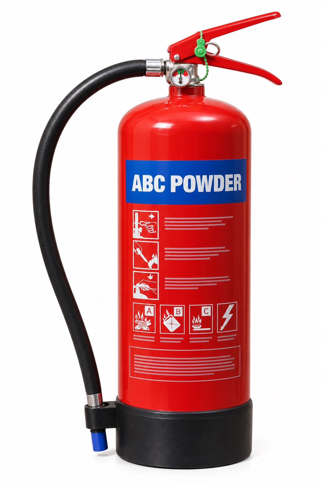
ABC dry powderBlue panel / ABC POWDER
A, B and C if marked
Interrupts flame chemistry; multipurpose powder also acts on Class A material. A C marking does not authorise tackling a gas leak.
Check the limitation
Powder can obscure escape and impair breathing; it is not generally recommended indoors. Limited cooling allows reignition. It is not metal-specific D powder or a substitute for F-rated cooking-oil equipment.
Parts in text
Cylinder
The pressure vessel holds the agent and propellant as designed. Report corrosion, dents or other damage. Do not open, refill or repair it as an awareness check.
Agent name and colour marking
Read the actual agent name, fire ratings, electrical warnings and instructions. Colour is a recognition aid; it does not prove suitability. The illustration is not an operating label.
Fixed carrying handle
The lower fixed handle supports the unit. It is different from the upper operating lever. The exact grip and operation belong in practical instruction for the model.
Operating / squeeze lever
The upper lever operates the discharge valve when the safety device is released. Do not squeeze or discharge a unit to test it during a routine visual check.
Safety pin and pull ring
The pin mechanically prevents accidental operation. A pin or ring that is missing, distorted or insecure needs reporting; its presence does not prove the unit is serviceable.
Tamper indicator / snap-lock seal
The breakable indicator or snap-lock seal shows possible disturbance. Designs can use a separate pin-retaining strap or a pin-mounted indicator. It is different from the mechanical safety pin and is not a theft lock. Report it if broken or missing.
Pressure gauge
On this stored-pressure example the gauge indicates pressure, not the mass of agent remaining. A pointer in the marked range does not prove the cylinder is full or the unit has passed its service checks.
Hose, nozzle or applicator
The flexible hose ends in the model’s discharge nozzle. The clip is for stowage; a hose being clipped in place is not a service check. Do not block, detach or test-discharge it during a visual inspection.
Base / protective boot
The boot protects the base on this example. Other models have a different foot arrangement or no separate boot. Check the approved mounting and access rather than guessing from the picture.
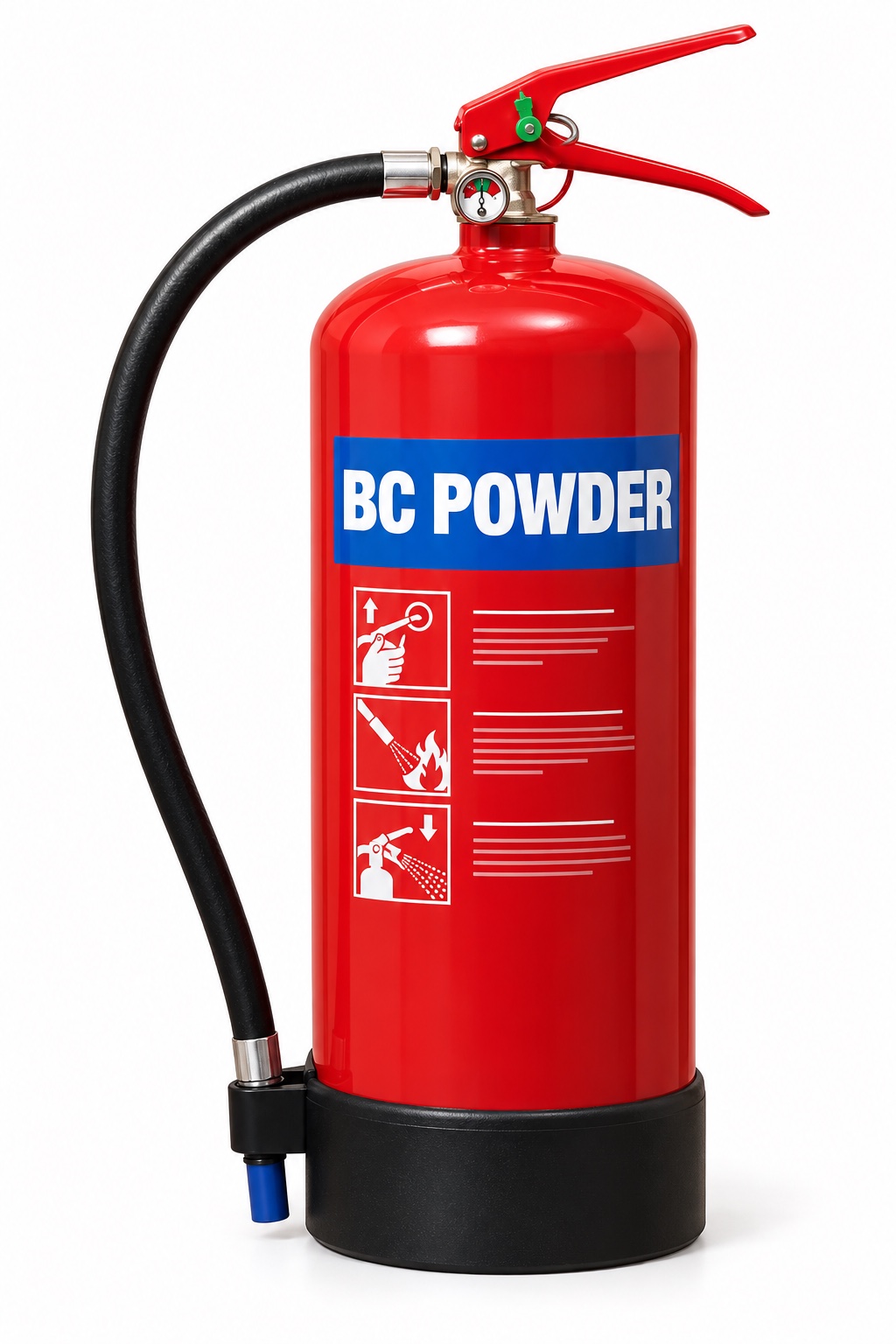
BC dry powderBlue panel / BC POWDER
B and C if marked; not A
Selected for particular liquid or gas hazards under the assessed plan. Electrical use must follow the actual unit’s instructions.
Check the limitation
Do not assume all blue powder extinguishers protect wood or paper. It has the visibility, breathing and reignition limitations of powder; it does not provide Class D or F protection.
Parts in text
Cylinder
The pressure vessel holds the agent and propellant as designed. Report corrosion, dents or other damage. Do not open, refill or repair it as an awareness check.
Agent name and colour marking
Read the actual agent name, fire ratings, electrical warnings and instructions. Colour is a recognition aid; it does not prove suitability. The illustration is not an operating label.
Fixed carrying handle
The lower fixed handle supports the unit. It is different from the upper operating lever. The exact grip and operation belong in practical instruction for the model.
Operating / squeeze lever
The upper lever operates the discharge valve when the safety device is released. Do not squeeze or discharge a unit to test it during a routine visual check.
Safety pin and pull ring
The pin mechanically prevents accidental operation. A pin or ring that is missing, distorted or insecure needs reporting; its presence does not prove the unit is serviceable.
Tamper indicator / snap-lock seal
The breakable indicator or snap-lock seal shows possible disturbance. Designs can use a separate pin-retaining strap or a pin-mounted indicator. It is different from the mechanical safety pin and is not a theft lock. Report it if broken or missing.
Pressure gauge
On this stored-pressure example the gauge indicates pressure, not the mass of agent remaining. A pointer in the marked range does not prove the cylinder is full or the unit has passed its service checks.
Specialist low-velocity applicator
The specialist applicator places the compatible metal-fire agent without unnecessarily disturbing burning material. Both agent and application method must suit the specific metal; this is not an ABC powder nozzle.
Base / protective boot
The boot protects the base on this example. Other models have a different foot arrangement or no separate boot. Check the approved mounting and access rather than guessing from the picture.
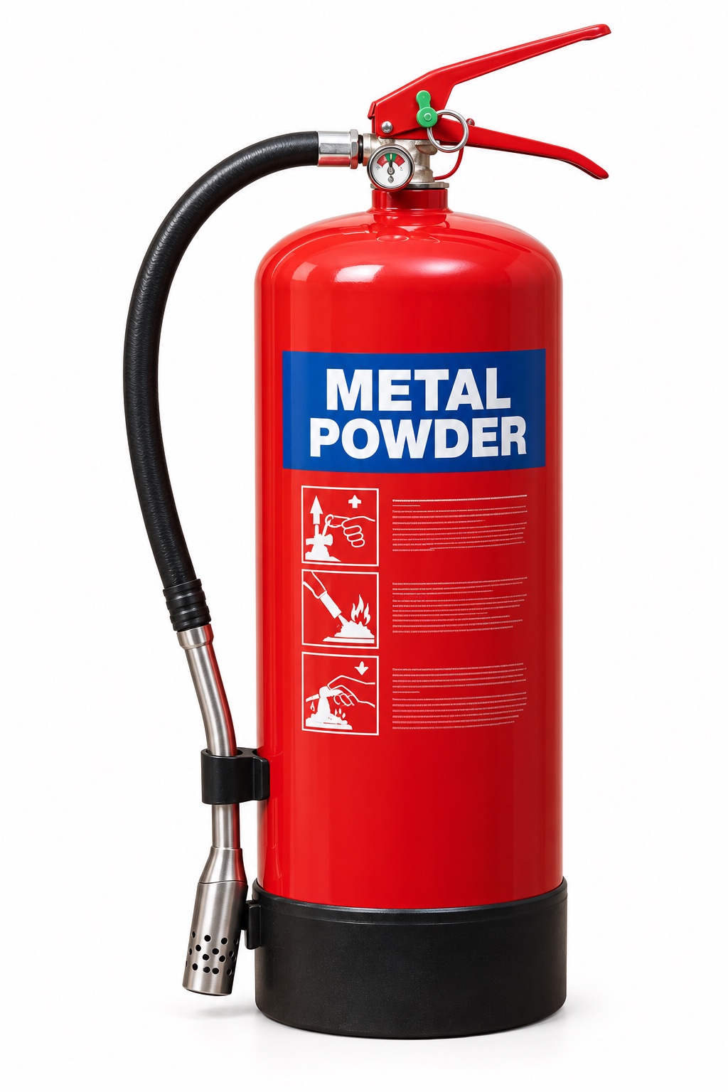
Class D specialist powderSpecific metal and agent named on label
D, for the specified metal
A specialist powder can isolate or absorb heat from a compatible burning metal. Selection requires knowledge of the metal and its form.
Check the limitation
The wrong powder can fail or react. Water, foam and CO₂ can be dangerous on certain burning metals. A powder suitable for magnesium is not automatically suitable for metallic lithium.
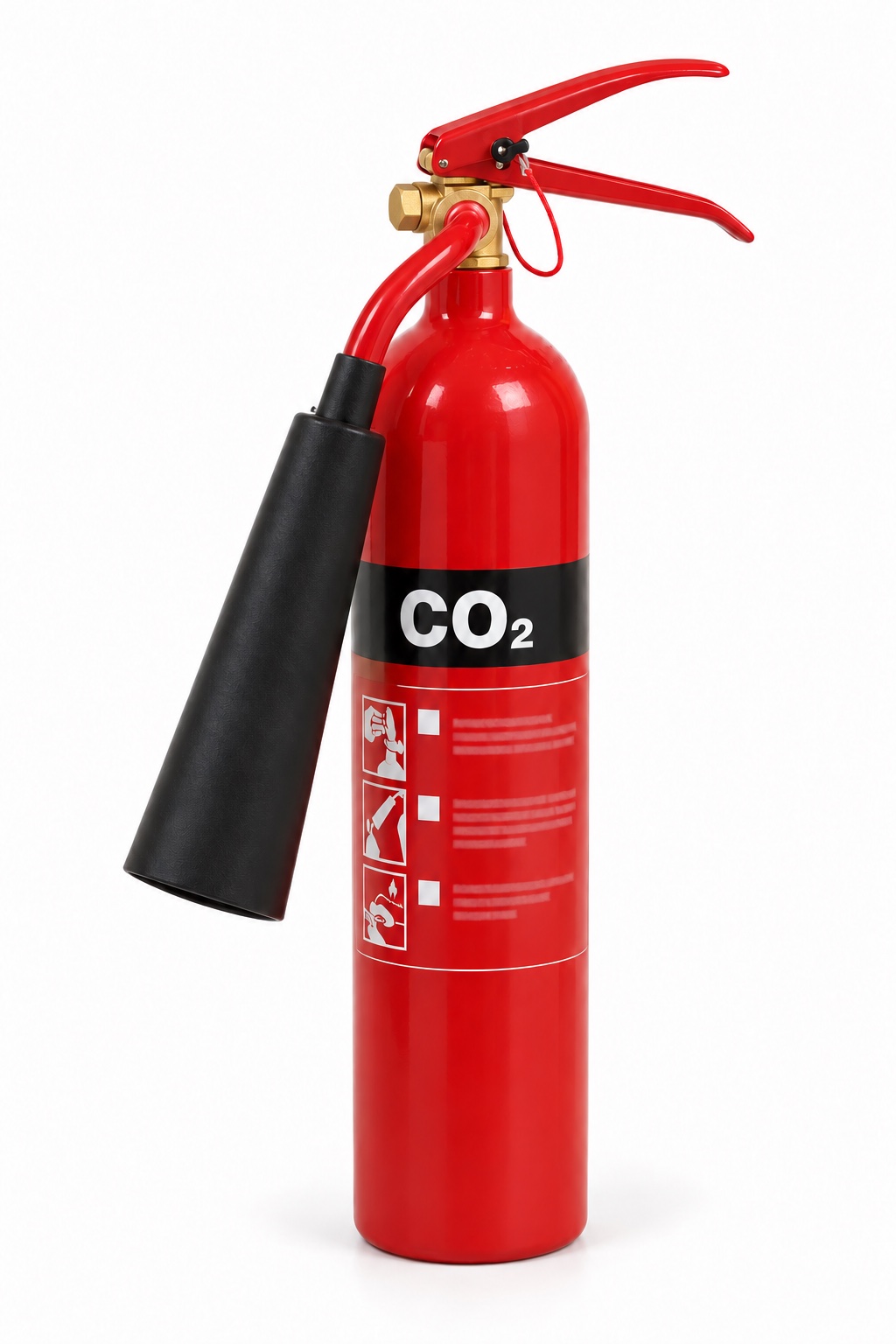
Parts in text
Cylinder
The narrow steel cylinder contains carbon dioxide under pressure. There is normally no pressure gauge on this portable type; service assessment includes the appropriate mass and integrity checks by competent personnel.
Agent name and colour marking
Read the actual agent name, fire ratings, electrical warnings and instructions. Colour is a recognition aid; it does not prove suitability. The illustration is not an operating label.
Fixed carrying handle
The lower fixed handle supports the unit. It is different from the upper operating lever. The exact grip and operation belong in practical instruction for the model.
Operating / squeeze lever
The upper lever operates the discharge valve when the safety device is released. Do not squeeze or discharge a unit to test it during a routine visual check.
Safety pin and pull ring
The pin mechanically prevents accidental operation. A pin or ring that is missing, distorted or insecure needs reporting; its presence does not prove the unit is serviceable.
Tamper indicator / snap-lock seal
The breakable indicator or snap-lock seal shows possible disturbance. Designs can use a separate pin-retaining strap or a pin-mounted indicator. It is different from the mechanical safety pin and is not a theft lock. Report it if broken or missing.
Horn and designated insulated grip
The flared horn directs the CO₂ discharge. Discharge parts can become extremely cold. Only the parts identified by the manufacturer as safe to hold should be gripped; not every horn is frost-free.
Displaces the atmosphere around a small flame and leaves no powder residue. Often selected around electrical equipment.
Check the limitation
Poor cooling means reignition is possible. CO₂ can create a dangerous atmosphere in enclosed spaces; discharge can cause frostbite. Hold only the designated insulated parts. Not a cooking-oil or metal-fire substitute.
Parts in text
Cylinder
The pressure vessel holds the agent and propellant as designed. Report corrosion, dents or other damage. Do not open, refill or repair it as an awareness check.
Agent name and colour marking
Read the actual agent name, fire ratings, electrical warnings and instructions. Colour is a recognition aid; it does not prove suitability. The illustration is not an operating label.
Fixed carrying handle
The lower fixed handle supports the unit. It is different from the upper operating lever. The exact grip and operation belong in practical instruction for the model.
Operating / squeeze lever
The upper lever operates the discharge valve when the safety device is released. Do not squeeze or discharge a unit to test it during a routine visual check.
Safety pin and pull ring
The pin mechanically prevents accidental operation. A pin or ring that is missing, distorted or insecure needs reporting; its presence does not prove the unit is serviceable.
Tamper indicator / snap-lock seal
The breakable indicator or snap-lock seal shows possible disturbance. Designs can use a separate pin-retaining strap or a pin-mounted indicator. It is different from the mechanical safety pin and is not a theft lock. Report it if broken or missing.
Pressure gauge
On this stored-pressure example the gauge indicates pressure, not the mass of agent remaining. A pointer in the marked range does not prove the cylinder is full or the unit has passed its service checks.
Hose, lance and spray applicator
The hose feeds the long lance and purpose-designed applicator. It helps distinguish this kitchen-fire unit from an ordinary short-nozzle extinguisher. Use requires model-specific practical training.
Base / protective boot
The boot protects the base on this example. Other models have a different foot arrangement or no separate boot. Check the approved mounting and access rather than guessing from the picture.
Wet chemicalYellow panel / WET CHEMICAL
F; often A if marked
Cools cooking oil and creates a protective surface layer through reaction with the fat. Use only within the actual unit’s rating and instructions.
Check the limitation
Do not mistake it for a general liquid-fire or electrical extinguisher. Incorrect application or moving the fryer can splash hot oil; apparent flame-out does not establish safe temperature.
Parts in text
Cylinder
The pressure vessel holds the agent and propellant as designed. Report corrosion, dents or other damage. Do not open, refill or repair it as an awareness check.
Agent name and colour marking
Read the actual agent name, fire ratings, electrical warnings and instructions. Colour is a recognition aid; it does not prove suitability. The illustration is not an operating label.
Fixed carrying handle
The lower fixed handle supports the unit. It is different from the upper operating lever. The exact grip and operation belong in practical instruction for the model.
Operating / squeeze lever
The upper lever operates the discharge valve when the safety device is released. Do not squeeze or discharge a unit to test it during a routine visual check.
Safety pin and pull ring
The pin mechanically prevents accidental operation. A pin or ring that is missing, distorted or insecure needs reporting; its presence does not prove the unit is serviceable.
Tamper indicator / snap-lock seal
The breakable indicator or snap-lock seal shows possible disturbance. Designs can use a separate pin-retaining strap or a pin-mounted indicator. It is different from the mechanical safety pin and is not a theft lock. Report it if broken or missing.
Pressure gauge
On this stored-pressure example the gauge indicates pressure, not the mass of agent remaining. A pointer in the marked range does not prove the cylinder is full or the unit has passed its service checks.
Hose, nozzle or applicator
The flexible hose ends in the model’s discharge nozzle. The clip is for stowage; a hose being clipped in place is not a service check. Do not block, detach or test-discharge it during a visual inspection.
Base / protective boot
The boot protects the base on this example. Other models have a different foot arrangement or no separate boot. Check the approved mounting and access rather than guessing from the picture.
Clean agent / vaporising liquidRead the agent; no universal colour shortcut
Product- and jurisdiction-specific
Specialist low-residue agents may protect sensitive equipment. Confirm the UK-approved application and the manufacturer’s limits.
Check the limitation
Low residue does not mean safe to breathe. Do not copy a US A:B:C rating as UK gas-fire approval. Legacy halon is restricted to permitted critical uses and applicable deadlines.
Parts in text
Cylinder
The pressure vessel holds the agent and propellant as designed. Report corrosion, dents or other damage. Do not open, refill or repair it as an awareness check.
Agent name and colour marking
This generic illustration has a green agent area and boot inspired by the supplied product. Green is not a universal Class L identification code. Read the real product name, chemistry, battery limits and instructions.
Fixed carrying handle
The lower fixed handle supports the unit. It is different from the upper operating lever. The exact grip and operation belong in practical instruction for the model.
Operating / squeeze lever
The upper lever operates the discharge valve when the safety device is released. Do not squeeze or discharge a unit to test it during a routine visual check.
Safety pin and pull ring
The pin mechanically prevents accidental operation. A pin or ring that is missing, distorted or insecure needs reporting; its presence does not prove the unit is serviceable.
Tamper indicator / snap-lock seal
The breakable indicator or snap-lock seal shows possible disturbance. Designs can use a separate pin-retaining strap or a pin-mounted indicator. It is different from the mechanical safety pin and is not a theft lock. Report it if broken or missing.
Pressure gauge
On this stored-pressure example the gauge indicates pressure, not the mass of agent remaining. A pointer in the marked range does not prove the cylinder is full or the unit has passed its service checks.
Hose, grip and applicator
The illustrated hose has a coloured ribbed grip and a small application tip. This shows the hardware family, not a tested battery capability. Follow the instructions for the actual agent and generation.
Base / protective boot
The boot protects the base on this example. Other models have a different foot arrangement or no separate boot. Check the approved mounting and access rather than guessing from the picture.
Battery-specific suppression productsNamed formulation and tested application
Check independent scope and instructions
Some products use water-based cooling or specialist media such as aqueous vermiculite for specified battery scenarios. Selection depends on chemistry, capacity and location.
Check the limitation
A ‘lithium’ label is not proof it will stop thermal runaway in a large pack. Flame suppression may not prevent reignition or gas release. Do not approach, carry or submerge a failing battery as a learner exercise.
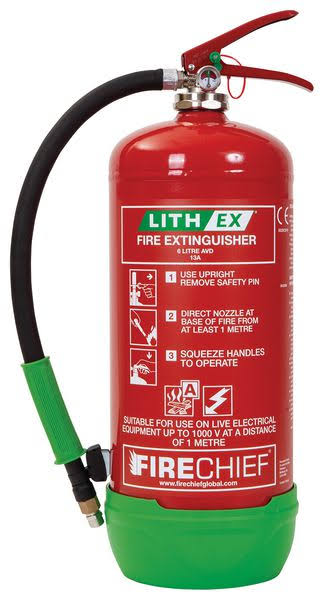
Lithium-ion product example · Firechief 6 L Lith-Ex
A named product example helps connect the generic table to an actual unit. Confirm the exact product before using its claims.
Agent and intended application
The linked Seton example uses aqueous vermiculite dispersion (AVD) for specified lithium-ion battery fire applications. Water content cools; the dispersed mineral helps form a barrier. This is not generic Class D metal-fire powder.
Read the actual rating
Seton lists a 6 L product with a 13A rating. That A rating describes its solid-material test performance; it does not, by itself, certify a universal Class L battery capability.
Match the exact model and generation
The manufacturer’s current 6 L G2 page identifies FLE6X and different discharge details from the retailer’s older listing. Do not mix their time, range or pressure values. Match the delivered label, product sheet and manual.
Check the battery scope
Confirm the allowed battery chemistry, energy capacity, state and scenario with the current manufacturer information and competent fire assessment. A large EV or energy-storage pack cannot be treated as a small-device fire.
Electrical conditions are product-specific
The supplied product label includes a voltage and minimum-distance condition. Do not transfer that condition to another battery extinguisher or infer that it makes an unsafe electrical approach acceptable.
After the flame disappears
Heat, off-gas and reignition can remain. Follow the planned withdrawal, exclusion and fire-service response; do not pick up, submerge or return a failed battery to charging.
Read the agent, fire-class letters, performance rating, electrical warnings, operating instructions and service condition. Numbers such as 13A or 55B describe standardised test performance, not a safe room size or permission to tackle that amount of fire. Colour is a clue; the actual label and assessed plan decide suitability.
What about a fire blanket?
A fire blanket is separate equipment, not an extinguisher type. It may be specified for a small contained cooking fire, but safe approach and the manufacturer’s limits still matter. Never carry a burning pan, improvise a cover or put yourself between fire and your exit.
Spot the dangerous assumption
Pause at each question, then open the explanation. These are unscored learning prompts alongside the course assessment.
A pan of cooking oil is burning. Would ordinary water help?
No. Rapid steam production can throw burning oil across the room. Raise the alarm and follow the kitchen emergency plan; never move the pan. Only a trained, authorised person should consider the specified F-rated equipment with a safe escape.
There is a C on the powder extinguisher. Should I put out the leaking gas flame?
Not as a routine response. Unburnt gas may continue escaping and form an explosive cloud. Withdraw, alarm and report the supply involved. Any safe isolation and specialist firefighting must follow the assessed emergency arrangements.
The flame around a battery has disappeared. Is the incident over?
No. Internal heat, flammable or toxic off-gas and reignition can remain. Keep clear, prevent access and tell the fire and rescue service what battery is involved. Flame-out is not permission to handle it or restart charging.
Both extinguishers have blue panels. Are the powders interchangeable?
No. Read ABC, BC or the exact Class D metal specification. Colour identifies a family; it does not establish the correct agent, rating or safe application.
A CO₂ extinguisher leaves no mess. Is it ideal in a small unventilated room?
No. A dangerous CO₂ concentration can incapacitate a person, while the fire and smoke already threaten escape. Do not enter an unsafe room. The fire plan and competent equipment selection must account for the space.
A water-mist product claims electrical suitability. Can I use any water extinguisher on a live cabinet?
No. Any tested electrical claim belongs to that particular model, with its own voltage and distance limits. It does not apply to ordinary water or another mist product, and it does not make an unsafe approach acceptable.
Source guidance and scope
UK learning context. Consult the applicable national fire guidance and your premises’ assessed plan. Manufacturer examples explain product variation; they are not product recommendations. Guidance checked 24 October 2026.
Define the fire-protection duty before counting equipment.
Existing SHAREhub photographic illustration. The written fictional case supplies the condition and decision evidence.
Understand the mechanism and the decision
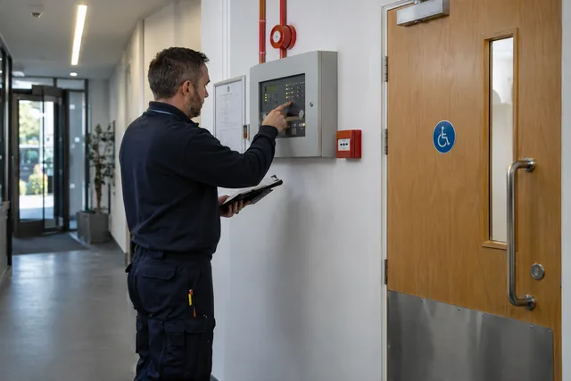
Active fire protection may detect an event, give warning or act to control a fire and its consequences. Its intended duty must match the actual hazard, people and equipment exposed. A system protecting premises escape has a different question from equipment intended to limit a major process event.
Identify the scenario, required response and supporting services before judging adequacy. The presence of alarms, hydrants or extinguishers is not proof that each credible event is covered. Competent design and assurance determine the required capability; workers need to understand what an impairment changes.
Verify the control in the actual task
Ask what the system must achieve, who owns its availability and what verification supports the current operating decision.
What should the active fire protection design basis include?
The design basis should explain which fire scenarios the system is intended to control and what performance is required.
A fire protection system can only be assured if its purpose is known. For example, a deluge system may be designed to cool an LPG vessel exposed to a pool fire, a foam system may be designed to control a tank fire, and a sprinkler system may be designed for a particular storage arrangement. If the process, inventory, storage height, rack layout, foam type, bund arrangement or emergency strategy changes, the design basis may no longer be valid.
The design basis should be controlled information. It should include drawings, calculations, standards, design assumptions, protected equipment, demand cases, water supply, foam demand, duration, power supplies, valve positions, alarm logic, testing requirements and impairment rules. Operators, engineers and emergency teams do not need every calculation, but they do need to know the system’s purpose and limits.
A competent design review should trace one credible fire from initiating release through ignition, detection, isolation, suppression or cooling, evacuation and environmental containment. Check common-cause demands such as loss of power or water, concurrent system use and access by responders. A drawing alone does not show delivered performance.
Applied case
A process release scenario is accepted solely because the building has several extinguishers.
Test the assumption
Only the equipment count. This does not establish acceptance. Quantity and appearance do not establish the required protective function.
Evidence before acceptance
Ask what the system must achieve, who owns its availability and what verification supports the current operating decision.
Test your decision
What must be established?
Only the equipment count.
Only whether the extinguishers look new.
The scenario-specific protective duty and evidence that the selected arrangements can perform it.
Compare the explanation
The scenario-specific protective duty and evidence that the selected arrangements can perform it.
Quantity and appearance do not establish the required protective function.
Connect detection and alarm to an effective response
Connect detection and alarm to an effective response.
Photorealistic illustrative UK workplace scene. Review checks: Avoid / redesign: Avoid the flammable transfer or redesign the operation so the dangerous inventory is not needed. Control the task: Separate tanks, transfer points and occupied routes; maintain suitable containment and remote isolation. Verify before release: Elimination may be impossible for the intended product; a replacement process must be assessed for new hazards.
Understand the mechanism and the decision
A detector must detect the intended condition within its relevant scope, and an alarm must reach people or systems able to respond as specified. Detection alone does not stop a leak or establish that the next protective action will occur.
The complete function can depend on coverage, communication, power, logic and response arrangements. A successful sound test may prove one part while leaving other questions open. Workers should know the expected response and report a missing or unreliable indication through the actual system.
Verify the control in the actual task
Compare the test record with the intended detection-to-response path and retain unverified elements as open questions.
What active fire protection systems should be considered?
The right system depends on the fuel, scenario, site layout, inventory, exposure, people at risk and emergency strategy.
Worked selection check: if a new polar solvent is introduced to a tank bund, do not infer that the existing hydrocarbon foam is compatible from its label or the presence of a foam tank. A competent reviewer must check the actual solvent, concentrate approval, proportioner, application method, duration, water supply and runoff plan before the transfer is accepted. The same system may be unsuitable for a different fuel or protected geometry.
There is no universal active fire protection package. Water may cool steel and extinguish ordinary combustibles but may spread some flammable liquid fires if used incorrectly. Foam may be essential for hydrocarbon pool fires but must be compatible with the fuel, application method, storage conditions and environmental constraints. Gaseous systems may protect electrical rooms but can be dangerous if occupancy controls are poor.
Selection should start with the fire-risk assessment, DSEAR assessment, process hazard analysis and emergency plan. The question is not simply what equipment is common in the industry, but what system is required to meet the performance needed for the credible scenario: extinguish, control, cool, prevent escalation, protect escape, protect responders or protect safety-critical equipment.
The choice of system should also consider how a fire will be discovered and who is expected to act. A remote tank compound may need flame detection, automatic deluge or monitors because a person may not be present when a release ignites. A workshop may rely on staff discovering a small fire quickly, but only if alarm, training, extinguisher type, escape and supervision are suitable. A warehouse may need sprinklers not because staff will fight the fire, but because early automatic control can prevent rapid spread before external responders arrive.
Systems should never be selected in isolation. Detection without alarm response is weak. Foam without reliable water and proportioning is weak. A hydrant network without access, maps, pressure, flow and responder familiarisation is weak. Good design joins the system, people, procedures, testing, emergency plan and management review into one dependable arrangement.
Photorealistic illustrative UK workplace scene. Review checks: Change at source: Avoid the flammable transfer or redesign the operation so the dangerous inventory is not needed. Make it observable: Elimination may be impossible for the intended product; a replacement process must be assessed for new hazards. Keep useful evidence: Change assessment, manufacturer evidence, commissioning result and approved transfer release.
Understand the mechanism and the decision
A fire-protection function may depend on water, power, valves, controls and access. Shared supplies can create a common limitation across apparently separate systems. A full tank or a running pump does not alone demonstrate availability of the complete required duty.
Assurance should cover the specified system and credible demands through competent methods. Do not infer capacity or acceptable pressure from a casual observation. Maintenance or an outage can change the protective state and needs the responsible impairment decision before affected work is accepted.
Verify the control in the actual task
Identify affected functions, assurance status and responsibility for accepting the resulting condition; the course does not specify firewater design values.
Why is firewater reliability critical?
Firewater reliability is critical because several active fire protection systems may depend on the same supply during the same emergency.
A firewater system includes more than a tank and pump. It may include water sources, suction arrangements, diesel and electric pumps, jockey pumps, pump houses, ring mains, sectional valves, hydrants, monitors, deluge valves, strainers, foam proportioners, test lines, standby power, fuel supplies and winterisation. A single closed valve, failed diesel start, blocked strainer or empty foam tank can defeat several downstream systems.
A no-flow pump start test may show that a pump starts, but not that water reaches the protected point at the required flow and pressure under credible simultaneous demand. The current design basis, manufacturer instructions and competent test plan determine what functional and flow evidence is needed. Check valves, hydrants, backup sources, alarms and known impairments as part of that assurance.
Sites also need to think about demand conflict. If sprinklers, monitors, deluge systems and emergency responders all draw from the same firewater network, the design must show that the system will not be starved during the credible scenario.
Firewater reliability checks
Firewater element
What can fail
Assurance evidence
Water source
Insufficient volume, poor replenishment, frozen supply or contaminated suction.
Tank level checks, capacity review, refill arrangements and inspection records.
Fire pumps
Failure to start, low flow, low pressure, fuel issue or maintenance defect.
Closed sectional valves, leaks, corrosion, pressure loss or poor labelling.
Valve line walks, lock/seal status, pressure tests and drawings.
Hydrants and monitors
Obstruction, damage, poor access, low pressure or poor reach.
Hydrant tests, monitor range checks, access inspections and responder drills.
Deluge and spray systems
Blocked nozzles, failed deluge valve, inadequate coverage or disabled actuation.
Functional tests, nozzle inspection, coverage checks and impairment records.
Common-cause dependencies
Power loss, flood, fire in pump house, cyber/control failure or multiple simultaneous demands.
Scenario testing, backup power checks, emergency exercises and design review.
Applied case
A planned utility outage is reviewed for production pumps but not for fire-protection dependencies.
Test the assumption
Only the production restart time. This does not establish acceptance. Protective dependencies need the same current plant-state information as production.
Evidence before acceptance
Identify affected functions, assurance status and responsibility for accepting the resulting condition; the course does not specify firewater design values.
Test your decision
What is the missing review?
The outage effect on required protection and the authorised operating restrictions or restoration.
Only the production restart time.
Only the water-tank appearance.
Compare the explanation
The outage effect on required protection and the authorised operating restrictions or restoration.
Protective dependencies need the same current plant-state information as production.
Manage protection impairment as an operating decision
Manage protection impairment as an operating decision.
Photorealistic illustrative UK workplace scene. Review checks: Setting: A planned tank transfer introduces a polar solvent to a protected bund; the outcome is to avoid assuming the existing hydrocarbon foam will work. Act: Verify the fuel identity and SDS, tank and bund scenario, foam concentrate approval, proportioner, application route, stock condition and runoff plan. Hold / review: Unknown fuel, obsolete foam approval, unverified mixing or no runoff route means no transfer on the assumption that any foam is suitable.
Understand the mechanism and the decision
A protective system can be impaired by isolation, failure, maintenance or changes to coverage. Recording the defect is only the beginning. The responsible review must decide what activities and occupancy are acceptable while the function is unavailable.
Temporary measures need an explicit justified scope and duration through the actual system; they are not automatically equivalent to the original protection. Restoration also requires verification and communication. Leaving an unresolved impairment off the next shift record can make an unsafe assumption look normal.
Verify the control in the actual task
State the unavailable function, restrictions, responsible decision and restoration evidence. Do not invent a substitute protective system as a learner exercise.
How should fire protection impairment be controlled?
Impairment control prevents a degraded fire protection system being treated as if it were still fully available.
A fire watch or temporary extinguisher does not automatically replace automatic detection, a sprinkler supply, deluge or exposure cooling. State exactly which scenario is no longer protected, what work must stop, who accepts residual risk, how people are informed and what test will end the impairment.
Impairment means a system is unavailable, partly unavailable or below its required performance. Examples include an isolated sprinkler zone, a disabled fire alarm detector, a drained fire main, a failed pump, out-of-service hydrants, foam concentrate unavailable, blocked access or maintenance work affecting a protected area.
The danger is normalisation. A short impairment can become accepted, a temporary isolation can be forgotten, or production can continue while a safety-critical mitigative barrier is unavailable. Impairments should therefore be risk assessed, authorised, time limited, communicated and compensated by temporary measures such as fire watch, reduced inventory, stopped hot work, standby resources or temporary detection.
The decision to continue operation during impairment should be made at the right level. Where the system protects a major accident scenario, the decision may need senior technical or operational approval, not only local maintenance sign-off.
Check combined impairments. A live firewater fault, disabled detection loop, unavailable foam stock or blocked responder access may affect the same scenario together. Before extending an impairment or changing plant, inventory, occupancy or work, reassess the combined loss of protection, renew the named approval and operating limits, and tell every affected shift and responder contact. Restore each dependent function and verify the complete barrier before closing the hold.
Fire protection impairment controls
Impairment control
What good looks like
Evidence
Identification
Any unavailable or degraded fire protection system is formally identified.
Impairment log, tag, alarm isolation record or defect report.
Risk assessment
The credible fire scenario and compensating measures are reviewed before continuing work.
Impairment risk assessment and temporary control plan.
Authorisation
The right level of management accepts the temporary risk.
Approval record with expiry date and operating limits.
Communication
Operators, maintenance, security, emergency team and affected contractors know the impairment.
Shift handover, permit notes, control-room log and emergency-team briefing.
Compensating measures
Extra fire watch, reduced inventory, stopped hot work, temporary equipment or restricted operations are applied.
Temporary control records and supervision checks.
Restoration and close-out
System is reinstated, tested and formally handed back.
Test record, close-out note and update to impairment register.
Applied case
A detector is covered during maintenance and the affected process is proposed for normal operation without a reviewed arrangement.
Test the assumption
The expectation that maintenance will finish soon. This does not establish acceptance. Future restoration and past performance do not establish present protection.
Evidence before acceptance
State the unavailable function, restrictions, responsible decision and restoration evidence. Do not invent a substitute protective system as a learner exercise.
Test your decision
What should govern that proposal?
The expectation that maintenance will finish soon.
The fact that the detector was reliable last month.
The authorised impairment assessment and required controls before the affected operation is released.
Compare the explanation
The authorised impairment assessment and required controls before the affected operation is released.
Future restoration and past performance do not establish present protection.
Recognise passive protection as a complete assembly
Recognise passive protection as a complete assembly.
Existing SHAREhub photographic illustration. The written fictional case supplies the condition and decision evidence.
Understand the mechanism and the decision
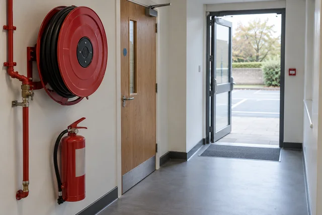
Passive fire protection resists or limits fire effects through its physical arrangement. Walls, doors, protected structures and penetrations can form part of a required barrier. Their performance depends on the whole suitable assembly and its installation, not simply on a surface label.
A fire door deliberately wedged against its accepted closing function may create a pathway. Conversely, an approved controlled hold-open arrangement must be assessed against its intended operation rather than assumed defective merely because the door is open. Observe the condition and compare it with the specified function.
Verify the control in the actual task
Use the barrier information and defect route; do not claim a fire resistance period or approved door configuration from appearance alone.
What does passive fire protection do?
Passive fire protection uses the building fabric, protective systems and separation to limit fire effects. It can delay heat damage, restrict fire or smoke spread and protect escape or critical plant, but it works only within its design conditions.
Best-practice guide · six simple steps
Best-practice guide: Passive Fire Protection, Layout and Separation
Start with the key actions, then explore value, a workplace example, harm, stronger controls and further help. Choose a step or use Previous and Next; the guide does not advance automatically.
Keep one card or the full set for social sharing, team briefings and learning. Each PDF contains one card per page. Read the full topic for explanations, questions and source links.
Read all six steps as text
1. What does passive fire protection do?
Passive fire protection uses the building fabric, protective systems and separation to limit fire effects.
Avoid / redesign: Avoid the new compartment breach or unnecessary occupied cabin; where feasible remove the flammable inventory or ignition-producing task.
Control the task: Separate occupied areas from credible effects and maintain complete compartment walls, doors and protected routes.
Verify before release: Approved alternative route or location and change record.
Passive fire protection uses the building fabric, protective systems and separation to limit fire effects. It can delay heat damage, restrict fire or smoke spread and protect escape or critical plant, but it works only within its design conditions. Passive fire protection uses fire-resisting construction, protective systems and plant separation to slow the spread of heat and smoke and limit escalation.
Apply it: Which part of this plan would you check at the workface before authorising the task?
2. Turn passive fire protection, layout and separation knowledge into a decision
Use the evidence to improve the actual work arrangement.
Change at source: Avoid the new compartment breach or unnecessary occupied cabin; where feasible remove the flammable inventory or ignition-producing task.
Make it observable: Approved alternative route or location and change record.
Keep useful evidence: Keep the location and penetration ID, design/system evidence, product identification, installer record, before-and-after photographs, inspection and acceptance, updated drawing and closure of the impairment.
Passive fire protection uses fire-resisting construction, protective systems and plant separation to slow the spread of heat and smoke and limit escalation. Its performance depends on complete compartments, suitable fireproofing, drainage and layouts matched to credible fire and explosion scenarios. Keep the location and penetration ID, design/system evidence, product identification, installer record, before-and-after photographs, inspection and acceptance, updated drawing and closure of the impairment.
Apply it: What evidence would show that the change improves this task, rather than only completing a record?
Fictional example: a practical application of the existing topic lesson.
Setting: Install a data cable through a warehouse compartment wall beside an occupied office and protected corridor.
Act: Consider a route that avoids a new breach.
Hold / review: Stop on unknown wall construction or material, unexpected services, unsupported product substitution, damage to the boundary or loss of the agreed route.
Keep the opening and work area within the assessed scope. Maintain escape routes, control waste and ignition sources, and record the installed system before it becomes hidden. The competent person checks the installation against the approved specification before concealment.
Apply it: At which point would you hold this example, and what evidence would allow it to proceed?
4. A breach lets fire and smoke cross the boundary
Connect the task, the route to the person and the control that can fail.
Defect: A propped door or unsealed penetration interrupts the intended separation.
Spread: Smoke, heat or flame can reach another compartment or escape route.
People: Occupants may be exposed before evacuation or protection arrangements can work.
A propped door or unsealed penetration interrupts the intended separation. Smoke, heat or flame can reach another compartment or escape route. Occupants may be exposed before evacuation or protection arrangements can work. Use the full topic for the detailed mechanism, task limits and source scope.
Apply it: Where is this harm route present in the actual work, and which control breaks it before anyone is exposed?
5. Choose controls for passive fire protection, layout and separation
Start with the stronger practicable options and verify their effect.
Eliminate: Avoid the new compartment breach or unnecessary occupied cabin; where feasible remove the flammable inventory or ignition-producing task.
Reduce or substitute: Use a less hazardous substance or process, or reduce stored inventory where technically feasible; review compatibility and any new hazard.
Isolate: Separate occupied areas from credible effects and maintain complete compartment walls, doors and protected routes.
Control — physical and engineered: Specify compatible fire-stopping, protected supports, drainage and, where required, detection or automatic isolation.
Control — administrative: Coordinate alterations, fire-risk and dangerous-substance assessments, impairment restrictions, inspection and handback.
Eliminate: Avoid the new compartment breach or unnecessary occupied cabin; where feasible remove the flammable inventory or ignition-producing task. Reduce or substitute: Use a less hazardous substance or process, or reduce stored inventory where technically feasible; review compatibility and any new hazard. Isolate: Separate occupied areas from credible effects and maintain complete compartment walls, doors and protected routes. Control — physical and engineered: Specify compatible fire-stopping, protected supports, drainage and, where required, detection or automatic isolation. Control — administrative: Coordinate alterations, fire-risk and dangerous-substance assessments, impairment restrictions, inspection and handback. Read the full control table for qualifications, ownership and verification. Use the actual task and applicable jurisdiction; existing technical approval remains unchanged.
Apply it: Which stronger option can be used here, and who will verify it before accepting the remaining risk?
6. Use the full passive fire protection, layout and separation lesson
Follow the official sources below and retain the task-specific evidence.
Official guidance: HSE explains passive protection performance and deterioration
Official guidance: HSE sets out the GB DSEAR control priorities
Task decision: Keep the location and penetration ID, design/system evidence, product identification, installer record, before-and-after photographs, inspection and acceptance, updated drawing and closure of the impairment.
Use the full topic for the decision points, practical examples, detailed control tables and source scope. HSE guidance applies to Great Britain; use HSENI for the Northern Ireland route and the source’s stated jurisdiction. A simplified guide does not change the page’s technical-review or approval status.
Apply it: Which official source and full-topic section will you use to resolve the next decision?
Simplified learning guide. Use the full topic, current official guidance and the actual work arrangements. Workplace scenarios labelled fictional are illustrative examples.
A compartment is a space enclosed by fire-resisting construction. Its walls, floors, doors, junctions and service openings must work together. A sound wall with an unsealed cable hole above a ceiling can still let fire or smoke bypass the intended boundary. A protective coating may slow heating of a steel support, but damage or unsuitable installation can leave the support vulnerable.
Passive measures do not normally need a powered pump or a person to start them. That does not mean nothing moves or changes: a fire door must close, and intumescent materials expand when heated. Alarms, sprinklers and deluge are active systems with different functions. Neither group automatically compensates for failure of the other.
On process sites, layout, separation, drainage and protection of occupied buildings also interrupt escalation: one release or fire must not readily defeat neighbouring equipment or the systems needed to control it. HSE explains passive protection performance and deterioration.
Applied case
A door required to close as part of the stated barrier is held by an unauthorised wedge.
Test the assumption
Only the door colour. This does not establish acceptance. The label does not compensate for a physical arrangement that defeats the required function.
Evidence before acceptance
Use the barrier information and defect route; do not claim a fire resistance period or approved door configuration from appearance alone.
Test your decision
What should be reported and resolved?
Nothing if a rating label remains visible.
The loss of the specified barrier function and the required protective arrangement.
Only the door colour.
Compare the explanation
The loss of the specified barrier function and the required protective arrangement.
The label does not compensate for a physical arrangement that defeats the required function.
Control penetrations and repairs against the tested system
Control penetrations and repairs against the tested system.
Photorealistic illustrative UK workplace scene. Review checks: Avoid / redesign: Avoid the new compartment breach or unnecessary occupied cabin; where feasible remove the flammable inventory or ignition-producing task. Control the task: Separate occupied areas from credible effects and maintain complete compartment walls, doors and protected routes. Verify before release: Approved alternative route or location and change record.
Understand the mechanism and the decision
A cable or pipe penetration can bypass a fire-resisting boundary if the sealing system is unsuitable or incomplete. The required solution depends on the barrier, service and tested or assessed installation basis. A red product or a filled-looking opening is not sufficient evidence.
Changes and repairs need competent specification, installation and inspection. Identify the system and its scope, and retain useful completion evidence. A photograph can support a record but cannot prove every hidden component or compatibility requirement.
Verify the control in the actual task
Check the specified assembly and required inspection evidence through responsible roles; an awareness learner does not approve a fire-stopping design.
How do you check that a proposed system is suitable?
Match the complete installed system to the required function, construction, services, exposure and conditions. A label, certificate, colour or headline rating alone cannot establish suitability.
For a penetration seal, the specialist needs the wall or floor type and thickness, opening dimensions, service types and sizes, supports, required fire performance and the manufacturer’s tested or assessed installation scope. For fireproofing, include the protected member or equipment, preparation, compatible layers, specified thickness and exposure, and any environmental or mechanical demands. In England, Approved Document B describes a tested sealing system for the relevant fire-resisting element; check its current edition and the actual building scope. Source: Approved Document B: fire safety (England); for process-equipment pool- or jet-fire exposure: HSE active and passive fire protection
Selection evidence that changes the decision
Question
Evidence to match
Hold condition
Does the evidence cover this configuration?
Current manufacturer instructions and the relevant test, classification or assessment for the full system.
A different substrate, service, support arrangement or undocumented substitution.
Does the test cover the fire scenario?
Specified performance for the applicable building, pool-fire or jet-fire exposure and required duration.
A building-fire rating offered as proof of jet-fire performance, or no design requirement.
Will it remain effective in service?
Weathering, corrosion, movement, damage and repair requirements considered for this location.
Damaged material, unknown coating system or repair outside the approved instructions.
Selection example: a contractor offers a seal labelled “120 minutes” for a new plastic pipe through a lightweight wall. The label does not establish whether that pipe, wall, opening and seal arrangement were covered, whether the relevant performance criteria are met, or whether the installed supports match. Hold installation or handback until the competent designer/installer resolves those points with the system evidence. “120 minutes” here is an example label, not a prescribed rating or a guaranteed escape time.
Use layout and separation for the actual consequence
Use layout and separation for the actual consequence.
Photorealistic illustrative UK workplace scene. Review checks: Change at source: Avoid the new compartment breach or unnecessary occupied cabin; where feasible remove the flammable inventory or ignition-producing task. Make it observable: Approved alternative route or location and change record. Keep useful evidence: Keep the location and penetration ID, design/system evidence, product identification, installer record, before-and-after photographs, inspection and acceptance, updated drawing and closure of the impairment.
Understand the mechanism and the decision
Layout can reduce exposure and escalation by considering hazardous inventory, occupied areas, neighbouring equipment and access. The relevant basis depends on the credible fire or explosion scenario. An empty space on a drawing is not automatically an adequate protective separation.
Temporary cabins, storage and work areas can alter occupancy or obstruct protection and emergency response. Review the change against actual consequences and dependencies. A generic distance copied from another plant or a course illustration cannot determine acceptance for the new arrangement.
Verify the control in the actual task
Obtain the current accepted location and restrictions, and communicate any effect on escape, access or the protective duty.
How can the ISO 45001 hierarchy of controls limit fire spread through layout, separation and passive protection?
First reduce the hazard and the chance of a release or ignition. Then select separation, containment and fire protection for the remaining credible events, including the people and safety systems they could affect.
For dangerous substances, consider removing or substituting the substance or process, reducing inventory, preventing releases, controlling releases at source and avoiding ignition. Keep incompatible substances apart. Mitigation then limits consequences. PPE does not replace a fire-resisting boundary, a protected route or appropriate siting. HSE sets out the GB DSEAR control priorities.
There is no safe separation distance for every tank, store or cabin. The assessor needs substance properties, quantities, operating conditions, release scenarios, topography, drainage, ventilation, neighbouring hazards, occupancy and emergency access. Select the applicable storage or design guidance and check its assumptions; HSG176 is a route for flammable-liquid tanks within its scope.
A hazardous-area zone addresses the likelihood and persistence of an explosive atmosphere and ignition control. Being outside a zone does not prove that an occupied cabin is outside fire, blast or toxic effects. Review the building, its occupants, air intakes and escape routes against the relevant scenarios. A new wall or cabin may also worsen congestion or trap vapour. HSE plant-layout guidance provides the design context.
Start with the strongest feasible change at source, then ask what barrier remains necessary. Eliminate or reduce the hazard where practicable; use engineering, separation and procedural controls for the remaining risk. PPE and work rules support these controls, but do not replace a failed physical fire barrier. GB control hierarchy: HSE hierarchy of risk controls
Here “Discipline” means dependable briefing, supervision and follow-through on a safe system, not blame. PPE and training support the physical and engineered controls; they cannot justify occupation behind a failed barrier. Each row identifies a practical check and a failure that requires a new decision.
How can the ERICPD hierarchy of controls limit fire spread through layout, separation and passive protection?
ERICPD is a planning crossmap. Its prompts do not add a sixth rung or rank Isolate above engineering. Discipline verifies and sustains every control level.
Worked activity: Example one Restoring a warehouse compartment
Activity and exposure
Install a data cable through a warehouse compartment wall beside an occupied office and protected corridor. Workers, visitors, delivery staff and contractors rely on that separation. The wall includes a concealed area above the ceiling; its construction must be confirmed.
Before work
Consider a route that avoids a new breach. Identify and photograph the location; agree isolation and access controls; arrange suitable reinstatement material and inspection before concealment. Confirm continued occupation and escape arrangements during the work, or restrict the affected area. Brief the contractor that a permit does not authorise an unassessed opening.
During the activity
Keep the opening and work area within the assessed scope. Maintain escape routes, control waste and ignition sources, and record the installed system before it becomes hidden. The supervisor checks interfaces with other trades and hands over any unfinished impairment at shift change.
Hold or stop
Stop on unknown wall construction or material, unexpected services, unsupported product substitution, damage to the boundary or loss of the agreed route. The premises lead and competent specialist must reassess before restart. Fire, smoke or an alarm triggers the emergency procedure, not a hurried repair.
Hand-back and release
The competent person checks the installation against the approved specification before concealment. Confirm surrounding junctions and doors remain effective, remove work obstructions and let the premises owner accept restoration. Do not return restricted areas to use while essential evidence or performance is unresolved.
Evidence to retain
Keep the location and penetration ID, design/system evidence, product identification, installer record, before-and-after photographs, inspection and acceptance, updated drawing and closure of the impairment. Record residual defects and restrictions explicitly.
Decision owner
Premises lead with competent fire-stopping specialist
Avoid the new compartment breach or unnecessary occupied cabin; where feasible remove the flammable inventory or ignition-producing task. This removes a route, receptor or initiating source.
Designer and premises or process owner.
Approved alternative route or location and change record. If the hazardous task remains, elimination has not been achieved. Sources: HSE sets out the GB DSEAR control priorities.
Reduce or substitute
Use a less hazardous substance or process, or reduce stored inventory where technically feasible; review compatibility and any new hazard. This reduces fuel or release potential, not the need for a sound barrier.
Process owner, purchaser and competent designer.
Substitution or inventory assessment, updated drawings and operating limits. Do not assume a replacement has lower total risk. Sources: HSE sets out the GB DSEAR control priorities.
Isolate
Separate occupied areas from credible effects and maintain complete compartment walls, doors and protected routes. This interrupts heat, smoke or blast exposure only within the assessed design conditions.
Competent fire/process designer; premises owner checks the installed arrangement.
Scenario-based siting and system evidence, field inspection. A zone boundary or nominal distance alone is insufficient; openings or blocked routes defeat isolation. Sources: HSE plant-layout guidance.
Control — physical and engineered
Specify compatible fire-stopping, protected supports, drainage and, where required, detection or automatic isolation. These limit spread or escalation; drainage may create a new route if its destination is wrong.
Engineering owner, system designer and competent installer.
Coordinate alterations, fire-risk and dangerous-substance assessments, impairment restrictions, inspection and handback. These keep physical barriers within their approved conditions.
Premises/process owner and supervisor.
Current drawings, permits, defect log, shift handover and acceptance. Paperwork cannot replace an absent seal or safe layout. Sources: Premises fire guidance.
Personal protective equipment
Use task-specific PPE for assessed maintenance residual risks and only with the other controls. Ordinary worker PPE cannot make an occupied cabin safe from a credible major fire or blast.
Supervisor selects and checks suitable equipment for the approved task.
Risk assessment, issue, fit and condition checks. PPE protects its wearer only and does not restore a compartment or protect all occupants. Sources: HSE sets out the general control hierarchy.
Discipline — reliable follow-through
Brief roles, supervise critical steps, report defects and stop work when assumptions change. This means dependable training and checks, not blame.
Manager and supervisor; workers report and follow agreed limits.
Briefing, inspection and close-out records; failed checks trigger reassessment. Behaviour alone cannot compensate for a failed physical barrier. GB hierarchy: HSE hierarchy of risk controls
How can the ISO 45001 hierarchy of controls limit fire spread through layout, separation and passive protection?
The hierarchy of controls in ISO 45001:2018 comes under Clause 8.1.2 (Eliminating hazards and reducing OH&S risks), which is located within Clause 8 ("Operation").
Worked activity: Example one Restoring a warehouse compartment
Activity and exposure
Install a data cable through a warehouse compartment wall beside an occupied office and protected corridor. Workers, visitors, delivery staff and contractors rely on that separation. The wall includes a concealed area above the ceiling; its construction must be confirmed.
Before work
Consider a route that avoids a new breach. Identify and photograph the location; agree isolation and access controls; arrange suitable reinstatement material and inspection before concealment. Confirm continued occupation and escape arrangements during the work, or restrict the affected area. Brief the contractor that a permit does not authorise an unassessed opening.
During the activity
Keep the opening and work area within the assessed scope. Maintain escape routes, control waste and ignition sources, and record the installed system before it becomes hidden. The supervisor checks interfaces with other trades and hands over any unfinished impairment at shift change.
Hold or stop
Stop on unknown wall construction or material, unexpected services, unsupported product substitution, damage to the boundary or loss of the agreed route. The premises lead and competent specialist must reassess before restart. Fire, smoke or an alarm triggers the emergency procedure, not a hurried repair.
Hand-back and release
The competent person checks the installation against the approved specification before concealment. Confirm surrounding junctions and doors remain effective, remove work obstructions and let the premises owner accept restoration. Do not return restricted areas to use while essential evidence or performance is unresolved.
Evidence to retain
Keep the location and penetration ID, design/system evidence, product identification, installer record, before-and-after photographs, inspection and acceptance, updated drawing and closure of the impairment. Record residual defects and restrictions explicitly.
Decision owner
Premises lead with competent fire-stopping specialist
Avoid the new compartment breach or unnecessary occupied cabin; where feasible remove the flammable inventory or ignition-producing task. This removes a route, receptor or initiating source.
Designer and premises or process owner.
Approved alternative route or location and change record. If the hazardous task remains, elimination has not been achieved. Sources: HSE sets out the GB DSEAR control priorities.
Substitution — actual replacement
Use a demonstrably less hazardous substance or process where feasible; review compatibility and new hazards. Inventory minimisation remains a separate inherent risk-reduction decision, not the substitution taught in this panel.
Process owner, purchaser and competent designer.
Substitution or inventory assessment, updated drawings and operating limits. Do not assume a replacement has lower total risk. Sources: HSE sets out the GB DSEAR control priorities.
Isolate
Separate occupied areas from credible effects and maintain complete compartment walls, doors and protected routes. This interrupts heat, smoke or blast exposure only within the assessed design conditions.
Competent fire/process designer; premises owner checks the installed arrangement.
Scenario-based siting and system evidence, field inspection. A zone boundary or nominal distance alone is insufficient; openings or blocked routes defeat isolation. Sources: HSE plant-layout guidance.
Control — physical and engineered
Specify compatible fire-stopping, protected supports, drainage and, where required, detection or automatic isolation. These limit spread or escalation; drainage may create a new route if its destination is wrong.
Engineering owner, system designer and competent installer.
Coordinate alterations, fire-risk and dangerous-substance assessments, impairment restrictions, inspection and handback. These keep physical barriers within their approved conditions.
Premises/process owner and supervisor.
Current drawings, permits, defect log, shift handover and acceptance. Paperwork cannot replace an absent seal or safe layout. Sources: Premises fire guidance.
Personal protective equipment
Use task-specific PPE for assessed maintenance residual risks and only with the other controls. Ordinary worker PPE cannot make an occupied cabin safe from a credible major fire or blast.
Supervisor selects and checks suitable equipment for the approved task.
Risk assessment, issue, fit and condition checks. PPE protects its wearer only and does not restore a compartment or protect all occupants. Sources: HSE sets out the general control hierarchy.
Discipline — reliable follow-through
Brief roles, supervise critical steps, report defects and stop work when assumptions change. This means dependable training and checks, not blame.
Manager and supervisor; workers report and follow agreed limits.
Briefing, inspection and close-out records; failed checks trigger reassessment. Behaviour alone cannot compensate for a failed physical barrier. GB hierarchy: HSE hierarchy of risk controls
Distinguish the decisions. Replacing a hazardous substance or process with a demonstrably less hazardous alternative is substitution. Reducing stored quantity is inventory minimisation: it is valuable inherent risk reduction, but is not itself substitution. Keep both decisions in the assessment and record compatibility, remaining release potential and the barrier still required.
Applied case
A temporary occupied cabin is proposed in an unused process area without a current consequence review.
Test the assumption
A distance guessed from an unrelated example. This does not establish acceptance. Space availability does not establish acceptable exposure or escalation control.
Evidence before acceptance
Obtain the current accepted location and restrictions, and communicate any effect on escape, access or the protective duty.
Test your decision
What is required?
A distance guessed from an unrelated example.
Only a check that the cabin fits.
The competent layout and occupancy review for the actual hazards and protective arrangements.
Compare the explanation
The competent layout and occupancy review for the actual hazards and protective arrangements.
Space availability does not establish acceptable exposure or escalation control.
Photorealistic illustrative UK workplace scene. Review checks: Setting: Install a data cable through a warehouse compartment wall beside an occupied office and protected corridor. Act: Consider a route that avoids a new breach. Hold / review: Stop on unknown wall construction or material, unexpected services, unsupported product substitution, damage to the boundary or loss of the agreed route.
Understand the mechanism and the decision
A barrier can be impaired by damage, an unreviewed opening, changes in use or adjacent work. The significance depends on what function the barrier must perform and which people or equipment it protects. Cosmetic appearance alone cannot establish priority or fitness.
Report precise location and observed condition without inventing a fire rating or hidden defect. The responsible review determines interim restrictions, repair specification and verification. A completed work order is not evidence of restored performance unless the required checks address the actual barrier.
Verify the control in the actual task
Retain the condition and review outcome in the current information so the next task does not assume a restored barrier prematurely.
What happens when a barrier is impaired?
An impairment is a loss or uncertainty in the protection being relied on. Stop the work that creates or worsens it, inform the responsible premises or process owner, and establish whether continued occupation or operation can be justified before proceeding.
The decision owner and competent specialist identify what is affected, who may be exposed, other unavailable safeguards and the credible consequences. They define any restrictions, temporary measures, repair route, reassessment triggers and handover requirements. Restrict use or shut down through the approved safe procedure where necessary; do not improvise a shutdown that creates another hazard.
An extra patrol, a permit or a promised repair is not proof that a missing compartment or damaged support remains safe. Temporary measures must be justified for the actual scenario, remain effective and have an owner and expiry or review condition set by the assessment. Tell affected workers, contractors and neighbouring occupiers. A shift change must not erase the restriction.
If there is fire, smoke, a leak or an alarm, follow the site emergency arrangements: raise the alarm, leave by a safe route, summon emergency help and report at the designated place. Do not delay evacuation to repair protection or operate an unfamiliar drain or valve. Give responders the location, substance information and known impairments from safety; re-entry requires the authorised all-clear. Premises fire guidance and DSEAR emergency duties support planning for these events.
Applied case
A newly drilled opening crosses a boundary whose protective function is still required.
Test the assumption
Assume a small opening is always insignificant. This does not establish acceptance. The effect and repair need the actual system basis.
Evidence before acceptance
Retain the condition and review outcome in the current information so the next task does not assume a restored barrier prematurely.
Test your decision
What is the defensible action?
Fill it with any available material and close the record.
Raise the barrier impairment for responsible assessment and a verified repair/operating decision.
Assume a small opening is always insignificant.
Compare the explanation
Raise the barrier impairment for responsible assessment and a verified repair/operating decision.
The effect and repair need the actual system basis.
Existing SHAREhub photographic illustration. The written fictional case supplies the condition and decision evidence.
Understand the mechanism and the decision
Preventing an explosive atmosphere or controlling ignition addresses the event before damaging pressure develops. Relief, isolation, suppression or resistant equipment may limit particular consequences within a defined basis. They are not interchangeable labels for one universal solution.
The selected functions must match the material, connected equipment and credible event. A protection device cannot justify ignoring the initiating conditions, and its presence cannot establish that all propagation routes are controlled. Competent design must address the complete system and limitations.
Verify the control in the actual task
Ask what each measure does, which scenario it covers and how its performance is verified.
Prevention and protection answer different questions
Prevention reduces the chance of a hazardous event; protection limits its effects. Both depend on the actual scenario, complete systems and current condition.
Fictional learning example
Separate the evidence from the decision
Part of the picture
What the example establishes
Prevention
Control releases, hazardous atmospheres and credible ignition sources.
Protection
Use suitable containment, separation, relief, suppression or isolation where the assessed design requires them.
Dependency
Firewater, detection, power, access or a damaged passive assembly may impair the claimed protection.
Pause and decide: Does counting installed devices establish that the escalation route is controlled?
Compare the reasoning
No. Check the required duty, system boundaries, dependencies, test evidence and current impairment status. For connected equipment, consider whether pressure or flame could propagate. A local protective device does not prove that the connected system is protected.
What do prevention, relief, isolation and suppression mean?
They are the main control families used to stop explosions occurring or reduce the harm if prevention fails.
Prevention controls the conditions needed for an explosion: fuel, oxidant, ignition, dispersion, confinement and process upset. Examples include substitution, closed handling, ventilation, inerting, dust control, leak prevention, hazardous area equipment, static control and hot-work permits. See HSE DSEAR in detail.
Relief and venting are mitigation controls. They do not stop ignition, but they aim to prevent equipment or structures being destroyed by pressure. Isolation prevents an explosion in one vessel or duct from propagating into connected plant. Suppression detects rapid pressure rise or flame and injects suppressant quickly enough to limit the event.
These controls are often interdependent. A dust collector may need housekeeping to prevent external dust layers, explosion relief to protect the collector, isolation to protect upstream equipment and maintenance to prove the system is ready.
Photorealistic illustrative UK workplace scene. Review checks: Avoid / redesign: Stop explosive atmosphere or ignition forming. Control the task: Stop flame and pressure propagation. Verify before release: Closed transfer, ventilation, inerting and ignition control.
Understand the mechanism and the decision
An explosion can propagate through connected ducts, pipes or equipment. A device protecting one enclosure does not automatically protect another. Isolation of explosion propagation is an engineered protective function, distinct from a normal process valve being present.
Changes to connected equipment or flow routes can challenge the existing basis. The responsible technical review must establish suitable integrated protection and assurance. Workers should report modifications and impairment, rather than selecting or adjusting an isolation device from a general course example.
Verify the control in the actual task
Keep configuration, device status and change acceptance current; do not infer performance from component names alone.
Why is explosion isolation needed?
Explosion isolation is needed to stop flame, pressure or burning material travelling through connected equipment.
Many dust and vapour systems are connected by ducts, pipework, conveyors or transfer lines. An explosion in one item of equipment can propagate into upstream or downstream equipment unless isolation is provided. See HSE preventing dust explosions.
Isolation can be mechanical, chemical or process-based depending on the system. Examples include fast-acting valves, flap valves, rotary valves, chemical isolation, flame arresters and process separation. The key issue is that the selected device must be suitable for the material, pressure, duct, direction of propagation and maintenance regime.
Dust extraction systems where flow direction suits.
Must be installed correctly and maintained.
Rotary valve
Powder transfer isolation where suitable.
Clearance, strength and material suitability matter.
Chemical isolation
Suppression agent stops propagation in duct.
Needs specialist design and maintained suppressant.
Flame arrester
Prevents flame transmission in some vapour systems.
Needs correct application and cleaning.
Physical separation
Layout reduces propagation and escalation.
Requires space and design discipline.
Applied case
A collector is connected to another vessel without reviewing the existing explosion-protection basis.
Test the assumption
Assume the original collector vent protects every connected vessel. This does not establish acceptance. Connected-system protection requires its own justified basis.
Evidence before acceptance
Keep configuration, device status and change acceptance current; do not infer performance from component names alone.
Test your decision
What should happen before accepting the changed arrangement?
Assume the original collector vent protects every connected vessel.
Treat any closed process valve as proven explosion isolation.
A competent integrated review of propagation, protection and required verification.
Compare the explanation
A competent integrated review of propagation, protection and required verification.
Connected-system protection requires its own justified basis.
Photorealistic illustrative UK workplace scene. Review checks: Change at source: Stop explosive atmosphere or ignition forming. Make it observable: Closed transfer, ventilation, inerting and ignition control. Keep useful evidence: Design assumptions, material data, drawings, commissioning tests, inspection records, impairment decisions and technical hand-back.
Understand the mechanism and the decision
A protective discharge can introduce a hazard outside the protected enclosure. The receiving area, people, connected routes and any backpressure or other design limitations matter to the protective basis. A device can exist yet be unsuitable for a changed location or connection.
Do not obstruct, redirect or extend a protective path without the required review. A convenient discharge route is not necessarily a safe route. The design and verification need competent assessment for the actual event and equipment; awareness training cannot size a vent or approve a discharge system.
Verify the control in the actual task
Verify that the accepted configuration and occupancy match the reviewed basis, and retain restrictions while the question remains unresolved.
What are the design limitations of explosion protection?
Design limitations are the assumptions that define when a protection system will and will not work.
A protection system is only as good as its assumptions. Dust particle size, moisture, explosibility, pressure rise, vessel volume, duct length, vent ducting, equipment strength, flow direction, maintenance condition and occupancy all affect whether the selected protection will work. See HSE explosion relief technical measures.
HSE explosion-relief and HSG103 material explains mechanisms and common design questions, but some referenced standards and COMAH-era wording are dated. A competent specialist must use current product, test and design standards for the actual dust or gas, protected volume, duct, vent path and occupancy. These pages supply no vent area, Kst or Pmax design calculation.
Teams should record the design basis in plain operational language. Operators and managers do not need every calculation, but they do need to know which changes trigger review: new material, new throughput, modified ducting, changed fan, different cleaning regime, blocked vent route or altered operating temperature.
Storage, ducting or building change blocks discharge.
Inspection and MOC.
Vessel strength
Corrosion, damage or unapproved repair.
Inspection and repair control.
Detection time
Sensor location or process change delays detection.
Functional testing and specialist review.
Isolation direction
Flow reversal or modified duct changes propagation.
Design review.
Occupancy
People moved into vent discharge zone.
Layout and people-at-risk review.
Illustrative seven-step decision route; this is a SHARE teaching example, not a prescribed legal checklist.
Step
Action
Check
Failure mode
Hold point
Avoid
Reduce combustible inventory or remove unnecessary open handling.
Design lead checks alternate process risk.
A substitute may create another hazard.
No substitution without reassessment.
Prevent atmosphere
Contain releases and control dust or vapour concentration.
Operations verifies enclosure and extraction.
A failed collector recreates the cloud.
Stop transfer on critical loss.
Control ignition
Match equipment and hot-work rules to actual hazardous zones.
Competent assessor checks site condition.
Product mark alone does not prove suitability.
No ignition-capable work in uncontrolled zone.
Choose protection
Specialist compares venting, isolation, suppression and resistant design.
Check Kst/Pmax or gas data, geometry and connected plant as applicable.
A vent may expose people or ducts may propagate flame.
Hold design without credible basis.
Verify installation
Confirm direction, protected volume and device interfaces.
Commissioning tests as-built connections.
A bypass or obstruction defeats function.
No start with unresolved defect.
Manage impairment
Track tests, maintenance, bypasses and changes.
Owner reviews test evidence and duration.
A stale design file conceals drift.
Stop or reduce operation on barrier loss.
Review
Reassess material, throughput, layout and incident learning.
Technical authority signs revised basis.
Old sizing may not fit new dust.
No restart before changed basis is approved.
Applied case
A protective outlet is redirected towards a regularly occupied access route during a layout change.
Test the assumption
Only whether the new duct looks tidy. This does not establish acceptance. The protective path and receiving environment are part of the safety function.
Evidence before acceptance
Verify that the accepted configuration and occupancy match the reviewed basis, and retain restrictions while the question remains unresolved.
Test your decision
What must be resolved?
Only whether the outlet remains visible.
The effect on protective performance and exposure through the competent change review.
Only whether the new duct looks tidy.
Compare the explanation
The effect on protective performance and exposure through the competent change review.
The protective path and receiving environment are part of the safety function.
Reconcile protection changes before restoration or release
Reconcile protection changes before restoration or release.
Existing SHAREhub 2D teaching schematic. Use alongside the explanation and fictional case in this lesson.
Understand the mechanism and the decision
Active protection, passive barriers and explosion-protection functions can share dependencies and affect the same scenario. Treating changes as isolated minor defects can miss the combined loss of protection. The operating decision needs the current complete protective state.
The stated change affects firewater availability, a fire-resisting penetration and a protection discharge route. Each requires an appropriate technical decision, and their interaction may affect allowable work or occupancy. Restoring one component does not automatically restore the whole accepted arrangement.
Verify the control in the actual task
Hand over the verified functions, open limitations and responsible acceptance. Course completion does not confer authority to certify protection or approve restart.
What are the before, during and after hold points?
Check the design duty and current condition before work; respond to degradation while work is underway; prove restoration before hand-back.
Before during and after fire barrier checks
Stage
Action
Stop or hold
Evidence
Before design or purchase
Name the fire scenario, people, fuel, system duty, design standard, water or agent supply and environmental route.
Control-room log, permit, interim controls and notifications.
After repair or change
Reinstate configuration and test the safety function at a suitable level, including alarm and response interfaces.
Do not remove the impairment tag on a visual check or reset alone.
As-left results, technical acceptance and hand-back.
After incident or exercise
Capture barrier demand, response, runoff and weak signals; resource and verify corrections.
Repeated defects or unclosed critical actions require management escalation.
Exercise or incident report and effectiveness review.
Applied case
Production proposes normal operation while the combined protection changes have no integrated acceptance.
Test the assumption
Release because each defect has a work-order number. This does not establish acceptance. Work orders and partial restoration do not establish the complete protective state.
Evidence before acceptance
Hand over the verified functions, open limitations and responsible acceptance. Course completion does not confer authority to certify protection or approve restart.
Test your decision
What is the defensible release decision?
Retain the affected restriction until the relevant reviews and verification support an accepted operating condition.
Release because each defect has a work-order number.
Restore one component and assume every related hold is closed.
Compare the explanation
Retain the affected restriction until the relevant reviews and verification support an accepted operating condition.
Work orders and partial restoration do not establish the complete protective state.
Study a completed fictional industrial construction and commissioning plan. Compare its warning, roles, accountability, responder access, rescue limits and recovery decisions with the learning above. It includes a new fictional site schematic, a worked exercise and separate blank recording annexes.
Use this as a teaching example when developing arrangements for your own premises. The fictional layout and role identifiers are not live emergency instructions.

 Recognise the fuel. Read the extinguisher. Protect your escape.