Independent SHAREhub awareness. This course does not provide a NEBOSH qualification, accreditation or authority to operate, design, isolate, test or maintain plant. Use competent site arrangements for real work.
This reader supplies the complete teaching. Use the interactive LMS course for assessed activities, saved progress and completion.
LESSON 1
Specify the outcome, not the equipment name
Explain the purpose of a safety-critical performance standard.
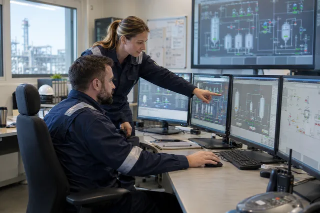
Existing SHAREhub photographic illustration. The written fictional case supplies the condition and decision evidence.
Understand the decision
A performance standard states what a safety-critical element must achieve for the relevant hazard and how that performance will be assessed. “Gas detector installed” describes equipment; it does not establish detection coverage, response or the protective action needed in the scenario.
Connect the function to the credible event and the people or assets protected. Identify the responsible owner and evidence needed through the lifecycle. This is awareness of the questions behind a standard, not authority to design a safety function or set its engineering acceptance criteria.
How should performance standards be structured?
The structure should connect the major accident scenario to a defined barrier function, testable criteria, evidence and impairment control.
Weak standards say things like 'maintain trip system' or 'fire pump available'. Strong standards define the hazard, demand scenario, required function, response time, capacity, environmental conditions, interfaces, proof test, owner, failure response and management-of-change trigger.
A standard should be understandable to the people who use it. Operators need to know why a bypass matters; technicians need clear test criteria; managers need to know which overdue defects require escalation; leaders need to see barrier health, not just maintenance activity.
Release, fire, explosion, toxic exposure, overpressure, loss of containment or escalation pathway.
Scenario register, HAZOP, bowtie, LOPA or safety report reference.
Credited barrier
A physical safeguard, human action or supporting arrangement relied upon in the scenario. Identify the narrower statutory SCE/SECE subset only where the applicable offshore regime requires it.
Barrier register and ownership.
Functionality
What the barrier must do and under what conditions.
Functional description, cause and effect, design basis or procedure.
Availability and reliability
When it must be ready and the confidence needed.
Test interval, failure data, proof-test record and outage control.
Survivability and independence
What challenge conditions and common-mode threats must be resisted.
Fire rating, separation, power/utility independence and cyber controls.
Verification
How performance will be checked and by whom.
Inspection, proof test, audit, field verification and competence evidence.
Impairment management
What happens if the barrier is failed, bypassed, unavailable or degraded.
Temporary controls, authorisation, risk assessment and restart rules.
Applied case
The register lists “emergency valve” without a required action or success criterion.
Required outcome
An equipment name does not define what protection the scenario needs.
Performance evidence
The standard connects the function to meaningful requirements and verification.
Test your decision
What is missing?
A defined protective function and evidence of the performance needed for its scenario.
Only a photograph of the nameplate.
A guarantee based on the word emergency.
Compare the explanation
A defined protective function and evidence of the performance needed for its scenario.
The equipment label does not define the outcome the system must deliver.
Recognise the meaning of function, availability, reliability, survivability and dependency.
Photorealistic illustrative UK workplace scene. Review checks: Avoid / redesign: Plan the test during a safe shutdown wherever practicable so testing does not leave operating plant dependent on the function being withdrawn. Control the task: Place affected equipment in the required safe state and control energy, inventory and access around moving shutdown equipment. Verify before release: If the hazardous step remains, keep it within the task assessment and select the stronger feasible remaining controls.
Understand the decision
Ask five connected questions. Functionality asks what the element must do; availability asks whether it is ready when needed; reliability concerns successful performance; survivability concerns performance under the relevant event conditions; interdependency identifies supporting systems or shared vulnerabilities.
These questions make an incomplete claim visible. A function can be correctly specified but unavailable during maintenance, or a tested component can lose its utility supply during the event it must control. A checklist heading is not evidence; each answer needs the applicable requirement and verification.
How does FARSI help define barrier performance?
FARSI turns a barrier name into measurable performance criteria.
Learners often memorise barrier names but miss performance. A fire pump, gas detector, trip, alarm or bund is only useful if it performs the required function at the time and under the conditions of the scenario. HSE offshore KP3 asset integrity report.
FARSI also helps challenge overclaiming. A human response to an alarm may be useful, but it should not be credited casually unless response time, workload, alarm clarity, training, staffing and recovery controls are credible.
FARSI element
Meaning
Example test question
Functionality
What the element must do.
What exactly must the gas detector detect, at what location and alarm level?
Availability
When the element must be ready.
Can the deluge system be unavailable during hot work or plant start-up?
Reliability
How likely it is to work on demand.
Does proof testing support the claimed risk reduction?
Survivability
Whether it survives the event conditions.
Will the cable, detector or valve survive fire, blast, flood or impact long enough?
Interaction/independence
Whether interfaces or common causes can defeat it.
Does it share power, software, instrument air or human response with another credited barrier?
Applied case
An isolation actuator works in a workshop but depends on air that the same fire scenario can disable.
Survivability
The function must perform in the event conditions for which it is credited.
Interdependency
A shared air or power failure can defeat otherwise working equipment.
Test your decision
Which performance question reveals this weakness?
Whether the actuator has passed routine mechanical servicing.
Interdependency and the required survival of the protective function under the event.
Whether the valve was the cheapest replacement.
Compare the explanation
Interdependency and the required survival of the protective function under the event.
The supporting supply and event conditions can determine whether a functioning component is useful.
Distinguish component evidence from protective-system evidence.
Photorealistic illustrative UK workplace scene. Review checks: Change at source: Plan the test during a safe shutdown wherever practicable so testing does not leave operating plant dependent on the function being withdrawn. Make it observable: If the hazardous step remains, keep it within the task assessment and select the stronger feasible remaining controls. Keep useful evidence: High-high trip detects level at defined set point and closes import valve within required time.
Understand the decision
The evidence pack should identify the function, current configuration, test scope, acceptance result, defects and restoration. Testing only a sensor or local actuator may leave the sensing-to-action path unproven. Records must say what was excluded rather than imply a broader pass.
Competent people define suitable inspection and proof testing for the actual system. Keep interval and design decisions within that authority. After work, confirm the function is restored from test mode or bypass and that any limitations are carried into the authorised operating decision.
What evidence should prove a safety critical element is healthy?
Evidence should show design basis, performance criteria, maintenance, proof testing, impairment control and management review.
A performance standard is only as good as the evidence behind it. A certificate or inspection record may show something was checked, but it does not always prove the right thing was checked against the right scenario. HSE offshore KP3 asset integrity report.
For major hazards, evidence should be traceable from the scenario through the credited barrier and into the live maintenance, inspection, operations and assurance systems.
Evidence item
What it proves
Weak signal
Major accident scenario reference
The barrier is linked to a credible hazard.
Barrier exists with no scenario owner.
Performance standard
Function, criteria and verification route are defined.
Standard uses vague words such as adequate or available.
Design basis
Capacity, set point, rating or response time is justified.
Design basis cannot be found or has changed.
Proof-test procedure
The test checks the actual safety function.
Test only checks part of the loop.
Inspection and maintenance record
Tasks are completed and defects managed.
Overdue tasks or repeat failures occur.
Bypass and impairment log
Unavailable barriers are authorised and risk assessed.
Bypasses are open-ended or poorly justified.
MOC record
Changes to plant, software, alarms, set points or procedures are reviewed.
Change occurs without reassessing the performance standard.
Applied case
A local valve movement test excludes the automatic demand path but is recorded as “system passed”.
Scope of proof
A component-only test must not be reported as a complete system pass.
Restored state
Record fault and bypass status as part of the available-function claim.
Test your decision
What should be corrected?
The automatic path can be assumed from local movement.
A higher pass percentage can compensate for the exclusion.
The claim must reflect limited coverage and the remaining unverified function.
Compare the explanation
The claim must reflect limited coverage and the remaining unverified function.
Evidence must match the function and the actual test scope.
Recognise different roles and possible shared failures.
A protective function needs sensing, decision-making and final action to achieve its specified outcome, with the required supporting services.
Understand the decision
Normal process control maintains operation; alarms alert people to a condition needing response; automatic shutdown functions can act through defined protective logic and final elements. These roles are related but not interchangeable. The design determines which functions are credited and how independence is achieved.
Two functions are not necessarily independent because they have different labels on a screen. Shared sensing, power, logic or final elements can create common failures. Learners should ask for the approved functional basis and current status rather than count screen icons as separate barriers.
Test the complete protective function
A protective function needs sensing, decision-making and final action to achieve its specified outcome, with the required supporting services.
Fictional learning example
Separate the evidence from the decision
Part of the picture
What the example establishes
Claim
A transmitter calibration has passed.
Not yet shown
The logic, final element and required safe outcome have not been demonstrated by that record.
Dependency
Loss of a shared power or air supply could affect several claimed functions.
Pause and decide: Can one healthy component establish the availability of the complete function?
Compare the reasoning
No. Check the applicable test scope and performance standard, including functionality, availability, reliability, survivability and interdependencies (FARSI). Record impairments and use the authorised operating review. A calibration or screen symbol establishes only the evidence it actually contains.
How do detection, process alarms and shutdown have different roles?
Detection recognises a condition; a process alarm prompts a defined operator action; a shutdown or trip is intended to move equipment or process toward a specified safe state.
The same gas detector may feed a display, an alarm, a ventilation action, an isolation valve and an emergency plan, but those are distinct functions. For each, define its initiating event, output, responsible person, dependencies and acceptable failure response. A manual action cannot be credited as though it were automatic without credible human response evidence.
A building fire alarm primarily warns relevant people to evacuate; a process alarm may require diagnosis and corrective action before a condition escalates. Fire-and-gas signals can do both. Interface design must prevent an operator misunderstanding a production alert as an evacuation instruction or missing a life-safety warning in an alarm flood.
Interpret a detector result within coverage, substance and condition.
Photorealistic illustrative UK workplace scene. Review checks: Avoid / redesign: Defer the detector work to a planned shutdown where practicable. Control the task: Apply the assessed process and energy isolations to the affected equipment, secure them against unintended operation and verify their effectiveness. Verify before release: Do not treat the hazard as eliminated if gas can remain, leak in or accumulate.
Understand the decision
A detector is selected and located for a defined hazard and response. Its effectiveness depends on what it detects, coverage, calibration or test condition, environment and the route by which a release reaches it. A favourable reading at one point does not prove every nearby space is free of hazard.
Moving a detector or changing the stored substance can alter the basis of detection. Use competent change review and required verification. A failed or obstructed detector should be treated through the impairment process; absence of an alarm is not proof that an unmonitored hazard is absent.
What can make a gas or flame detector miss the event?
A detector only works for the substance, release path and environmental conditions it was designed and maintained to sense.
Gas or vapour can disperse away from the sensor, stratify, be diluted or be blocked by equipment. Flame detection can depend on fuel and line of sight; smoke and heat devices respond differently in ventilation, dust, steam or high ceilings. A failed-zero reading, contaminated sensing head, lost power or unavailable communication path can look reassuring unless faults are made visible.
Use the actual scenario, fluid properties, ventilation, obstructions, weather, occupancy and response time in competent design and coverage assessment. Test that the device, logic, annunciation and final response work as intended; the page gives no generic placement, threshold, voting or proof-test interval.
Identify the full response and supporting services.
Photorealistic illustrative UK workplace scene. Review checks: Change at source: Defer the detector work to a planned shutdown where practicable. Make it observable: Do not treat the hazard as eliminated if gas can remain, leak in or accumulate. Keep useful evidence: The register has a named owner, review date, risk rating, control standard and action tracker.
Understand the decision
Cause-and-effect information connects a detected condition to alarms, shutdown actions and the intended safe state. The safe state is defined for the actual plant; “everything closes” is not a universal rule. Different equipment can need different responses and supporting services.
Trace the credited action through logic, final elements and utilities. Keep failures, inhibits and temporary changes visible. Before relying on restoration, use the specified verification and authorised hand-back. An awareness learner should not operate test switches or change logic to discover the intended response.
How should fire and gas cause-and-effect logic be controlled?
Fire and gas systems should connect detection to alarms, shutdowns and emergency actions through controlled cause-and-effect logic.
For a credible gas release during tanker transfer, trace the detector signal through logic and the control-room message to the isolation-valve command, then verify the valve actually closes and the process reaches its defined safe state. A hand-back record should show the tested initiation, each interface, the final element response, removed overrides and the operations lead accepting the restored function. A normal panel display alone proves none of those outcomes.
How should fire and gas cause-and-effect logic be controlled?
Control point
Expert detail
Evidence
Control pointDetector coverage
Expert detailCoverage should match credible releases, wind, congestion, ventilation and equipment layout.
EvidenceDetector mapping and design review.
Control pointAlarm handling
Expert detailOperators should know alarm priority, meaning, confirmation and escalation action.
EvidenceAlarm response procedures and drills.
Control pointShutdown logic
Expert detailTrip, isolation and emergency shutdown actions should match the hazard scenario.
EvidenceCause-and-effect matrix and proof-test record.
Control pointProof testing
Expert detailDetectors, alarms, logic solvers and final elements should be tested at defined intervals.
EvidenceProof-test plan and overdue-action dashboard.
Control pointImpairment management
Expert detailBypassed or failed detectors should trigger temporary controls and authorisation.
EvidenceImpairment log and reinstatement evidence.
Control pointProcess safety interface
Expert detailDetection should link to barrier registers, emergency plans and major accident scenarios.
Recognise why overload and routine silencing weaken response.
Photorealistic illustrative UK workplace scene. Review checks: Setting: A fictional process operator plans a test of a detector, logic and shutdown final element. Act: Coordinate the test with the control room, identify authorised inhibits and record which parts are simulated and which are physically verified. Hold / review: Keep the affected duty held if essential coverage or restoration evidence is missing; a simulation is not a complete proof test.
Understand the decision
An alarm needs a clear purpose, priority and understood response. Repeated nuisance alarms or a flood of indications can obscure the condition requiring attention. The operator’s workload, information and response time belong in competent alarm management rather than being treated as personal vigilance alone.
Use the current response instructions and report recurring problems. Acknowledgment or silencing does not prove that the process has recovered. Do not suppress an alarm informally to improve comfort or production; resolve its cause and any changed protection through the authorised process.
How should control rooms prevent an alarm flood from hiding a critical signal?
Every alarm should have a useful purpose and defined action; prioritisation and workload must remain usable during an abnormal event.
Standing, repeating and nuisance alarms can mask a new fire, gas or shutdown signal. A flood during an upset can exceed human diagnosis capacity. Record alarm rate, standing duration, suppressed state, operator response and real outcomes; investigate the initiating fault rather than teaching staff to acknowledge messages faster.
Rationalise alarms by consequence and required response, make safety-critical alerts distinct, keep response procedures current and resource the abnormal scenario. Shelving, suppression or mode changes need defined authority, visibility, expiry and return to service. Never silence or bypass a credited safety alarm for convenience.
Sources and references
Official context: HSE alarm management; HSE control systems. Check the stated jurisdiction and premises; practical examples require a competent site assessment.
Applied case
A recurring gas fault is routinely silenced so the control room can concentrate.
Actionable warning
An alarm needs understood priority and response, not merely an audible sound.
Recurring fault
Routine silencing can hide degraded information or protection.
Test your decision
What should be challenged?
The unresolved fault and loss of effective warning or protective information.
Only whether the alarm sounds pleasant.
The idea that recurring alarms deserve review.
Compare the explanation
The unresolved fault and loss of effective warning or protective information.
Repeated silencing can normalise a failed information or protection function.
Distinguish relief protection from normal process control.
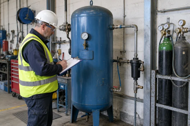
Existing SHAREhub photographic illustration. The written fictional case supplies the condition and decision evidence.
Understand the decision
Relief protection addresses specified overpressure or underpressure scenarios through a suitable designed system. Its basis depends on the actual equipment, material, credible event and discharge arrangements. A relief valve is not a normal operating control and cannot be assumed to cover every pressure-generating event.
Different event mechanisms may need different engineering measures; pressure relief and explosion protection are not interchangeable labels. Awareness learning should identify the scenario and evidence questions, not size devices or select setpoints. Changes to process service can invalidate the original protective basis.
Which overpressure scenarios must be considered?
Relief protection is only credible when the design scenarios have been identified and kept current.
A relief device sized for one scenario may be inadequate for another. Common cases include blocked outlet, control valve failure, external fire, tube rupture, utility failure, runaway reaction, thermal expansion, gas breakthrough, liquid overfill, reverse flow, abnormal start-up and failure of cooling or agitation. Process safety reviews should ask which cases apply, which case governs capacity and whether plant changes have altered the answer.
This is where management of change becomes critical. A new feedstock, increased throughput, changed solvent, modified control valve, higher storage temperature, new tie-in or changed flare load can invalidate an old relief calculation. Relief basis documents should therefore be living process safety information, not archive material.
Scenario
How pressure rises
What to verify
Blocked outlet
Flow continues into closed or restricted system.
Relief capacity, isolation practices and operating procedure.
External fire
Heat input vaporises contents and raises pressure.
Fire case sizing, emergency response and depressurisation need.
Thermal expansion
Blocked-in liquid expands as temperature rises.
Thermal relief on trapped liquid sections.
Runaway reaction
Heat/gas generation exceeds cooling/control.
Reaction relief basis, vent sizing and quench/emergency systems.
Tube rupture
High-pressure side enters lower-pressure equipment.
Relief capacity and isolation/interlock response.
Utility failure
Cooling, instrument air or power failure creates abnormal state.
Fail-safe positions and emergency operating procedures.
Overfill
Liquid enters vapour relief path or vent system.
Level trips, alarms, independent protection and disposal route.
Include normal venting and underpressure/vacuum scenarios for relevant low-pressure storage. An overpressure-only review is incomplete, and explosion relief has different response assumptions. Keep competent design/manufacturer review; historic standard editions quoted in older guidance are not automatically current.
Applied case
A process change adds a new pressure-generating scenario, but the team assumes the existing relief device covers it.
Scenario basis
A relief device is selected for defined pressure conditions, not every conceivable event.
Distinct mechanisms
Pressure relief and explosion protection cannot be treated as interchangeable labels.
Test your decision
What is needed?
Only confirmation that a valve is present.
Competent review of whether the relief basis remains suitable for the changed scenario.
A larger label reading safety valve.
Compare the explanation
Competent review of whether the relief basis remains suitable for the changed scenario.
The presence of a device does not prove coverage of a different event.
Recognise why the relief path extends beyond the device.
Photorealistic illustrative UK workplace scene. Review checks: Avoid / redesign: Eliminate: the process designer removes a blocked-in liquid segment where possible by redesigning the transfer path and minimising dead legs. Control the task: Isolate and engineer: a competent engineer sizes the relief device, inlet and outlet for the governing scenario and routes discharge to a verified safe system. Verify before release: Read the full task example, checks and stop points on this page.
Understand the decision
A relief system must provide a suitable complete route for the discharged material. Downstream pipework, shared headers, treatment or disposal systems and their availability affect the protective function and potential exposure. A device opening does not make its contents harmless.
The competent design establishes a safe destination and capacity for the relevant scenarios. Unknown connections, blockage or an unavailable downstream system need resolution. Do not discharge to an occupied area or improvise a vent route; the awareness task is to identify the gap and use the responsible review process.
How should venting and relief disposal be judged?
The discharge route is part of the protection system, not an afterthought.
A relief device that vents toxic, flammable, hot, cold or two-phase material into an unsafe location can convert overpressure protection into a different major accident scenario. Disposal assessment should consider people nearby, ignition sources, occupied buildings, drains, low points, wind, radiation, toxic exposure, noise, cold embrittlement, liquid carryover and environmental impact.
Flares, vents, scrubbers and blowdown systems have their own failure modes. A flare with failed pilots, liquid carryover, inadequate capacity or poor knockout is not a healthy barrier. A vent stack with poor dispersion may expose workers. A scrubber may not have the capacity, reagent or monitoring needed for the relief scenario.
Recognise different protective purposes without inventing a response.
Photorealistic illustrative UK workplace scene. Review checks: Change at source: Eliminate: the process designer removes a blocked-in liquid segment where possible by redesigning the transfer path and minimising dead legs. Make it observable: Read the full task example, checks and stop points on this page. Keep useful evidence: Management-of-change scope, LPG properties and scenario basis, vessel/relief calculations, flare study, proof-test records, lineup check, training and signed readiness release.
Understand the decision
Emergency depressurisation deliberately reduces hazardous pressure or inventory according to a designed strategy. Pressure relief protects against specified pressure conditions; normal venting serves another defined duty. These functions can interact but are not interchangeable or automatically safe to initiate manually.
The action can create downstream flows, noise, thermal effects or other hazards that the design and procedure must address. Use the applicable site emergency arrangements and authorised roles. A course example must never become an instruction to open a valve or dump inventory when the correct system and destination are unknown.
What do learners commonly confuse?
Pressure protection concepts are easy to memorise but harder to apply without scenario thinking.
Confusion
Better explanation
Professional test
PSV equals safe
A PSV is one component; the relief path and disposal route also matter.
Can the full route handle the credible scenario?
Relief prevents the incident
Relief usually mitigates overpressure after an initiating event.
What prevention barriers failed first?
Venting is always safe
Venting can create toxic, flammable, hot, cold or environmental hazards.
Where does the material go and who could be exposed?
Depressurisation is just opening a valve
Rate, route, low temperature, disposal and operator action matter.
Is the blowdown basis proven?
Written scheme covers all
The written scheme must be matched to real equipment and protective devices.
Does field condition match the scheme?
Applied case
A colleague suggests opening any available vent to reduce pressure during an abnormal condition.
Depressurisation
A designed pressure/inventory reduction strategy differs from routine venting.
No improvised release
An unidentified outlet cannot substitute for the applicable engineered response.
Test your decision
What should the learner recognise?
An improvised vent action can create new hazards and is outside the defined protective strategy.
Any open outlet is equivalent to engineered depressurisation.
The nearest drain is always an acceptable destination.
Compare the explanation
An improvised vent action can create new hazards and is outside the defined protective strategy.
Only the applicable designed system and authorised response can establish a defensible action.
Keep protection status explicit during faults, tests and bypasses.
Photorealistic illustrative UK workplace scene. Review checks: Function: High-high trip detects level at defined set point and closes import valve within required time. Independence: Trip independence from normal level control is defined and verified. Testing: Proof test covers sensor, logic, final element, alarm and valve response.
Understand the decision
When a credited element is unavailable, the site must assess the affected scenarios and define the authorised operating restriction or safe state. Temporary compensating measures need a justified basis and controlled life; a note that staff will be careful does not automatically replace an engineered function.
Record the impairment, owner, conditions and review point. Following repair or testing, verify restoration of the required configuration and function. A cleared fault lamp or reset command is narrower evidence than successful recovery of the complete protective function.
How should bypass and impairment be controlled?
A safety critical barrier that is bypassed, failed or degraded should trigger formal risk review and clear authority.
Barrier impairment is a live risk condition. The plant may look normal, but the protection layer has changed. Controls should define what can continue, what must stop, what temporary controls are acceptable and who can authorise exceptions. HSE HSG254 process safety indicators.
The hardest failures are often tolerated impairments: alarms inhibited for nuisance, trips bypassed for production, fire systems isolated during maintenance or proof tests deferred because shutdown is inconvenient.
Keep the affected operation stopped until restored, or until competent assessment demonstrates an acceptable restricted state with effective compensating protection, defined limits and authorisation.
Barrier is credited for a major accident scenario.
Safety trip bypassed
Require time-limited authorisation, compensating measures and operator briefing.
Bypass extends beyond agreed time or becomes routine.
Fire/gas detection unavailable
Review hot work, occupancy, ignition sources and emergency response.
Detector protects occupied or high-hazard area.
Relief or vent system defect
Check safe operating limits and loading conditions immediately.
Overpressure scenario can occur before repair.
Procedure unavailable or unvalidated
Do not rely on informal memory for safety critical tasks.
Start-up, line breaking, isolation or abnormal operation is affected.
Common utility failure
Review all barriers dependent on the same power, air, network or cooling source.
Multiple credited barriers share the same vulnerability.
Applied case
A bypass remains active after maintenance even though the local fault display has cleared.
Impairment
An unavailable credited function needs an accountable operating decision and restrictions.
Reset
Clearing a lamp does not establish that the required function is restored.
Test your decision
What needs verification?
Only whether the display can be acknowledged.
The credited function and configuration are actually restored before being relied on.
Nothing once the maintenance invoice arrives.
Compare the explanation
The credited function and configuration are actually restored before being relied on.
Resetting an indication does not establish restoration of a bypassed safety function.
Integrate standard, current state, test evidence and dependencies.
Existing SHAREhub 2D teaching schematic. Use alongside the explanation and fictional case in this lesson.
Understand the decision
Assurance asks whether each credited protective function has an applicable requirement, responsible owner and current evidence that it can perform. Trace the entire claim rather than accepting a list of installed devices or a high maintenance-completion rate. Separate known faults from unconfirmed coverage and record both honestly.
For workplace transfer, choose a protective function you encounter and identify the questions you may ask within your role. Use fictional resources to practise the evidence trail. Do not design the function, change settings or certify performance because you completed an awareness course.
How should performance standards be assured?
Assurance should test whether the credited barrier can still perform its safety function in the real scenario.
Assurance should sample live safety critical elements and follow the chain from major accident hazard to field evidence. It should challenge whether inspection intervals, proof tests, bypass rules, competence and MOC are strong enough for the claimed risk reduction.
Third-line or specialist assurance is often needed where functional safety, structural integrity, fire and gas, emergency shutdown, relief systems or complex control systems are involved.
Assurance sample
What good looks like
Escalate if
Scenario trace
Every safety critical element links to a scenario and required function.
A barrier is maintained but not linked to hazard reduction.
Proof test quality
Test checks the safety function, criteria and response time.
Test is incomplete or not understood.
Defect management
Failures are risk assessed and repaired within controlled timescales.
Safety critical defects are overdue.
Bypass review
All bypasses are authorised, briefed, time-limited and reviewed.
Bypasses become routine or invisible.
MOC sampling
Changes update performance standards and test procedures.
Change affects set point, logic, capacity or independence.
Leadership review
Barrier health appears in process safety dashboards.
Leaders only see maintenance completion rates.
Applied case
The moved detector, local-only valve test and unknown relief header all appear as complete on the dashboard.
Assurance claim
Trace the requirement through current configuration, tests, dependencies and restoration.
No average barrier
Unrelated completed jobs cannot compensate for an unproven necessary function.
Test your decision
What should the review do?
Accept three complete labels as three effective independent barriers.
Average the three labels into a passing score.
Challenge the scope and current evidence behind each protective claim before reliance.
Compare the explanation
Challenge the scope and current evidence behind each protective claim before reliance.
Different protective functions need their own applicable evidence and dependency checks.