Full public teaching and readers are free without an account. A free learner account is required for saved LMS progress and recorded assessment. Completion and any course-completion certificate depend on the configured LMS conditions. Open the course overview.
Lesson 1
Follow composite dust from source to exposure
Assess the material, process and travel path rather than judging exposure from visible housekeeping alone.
Locate the lungs, branching airways and diaphragm below them. The cutaway reveals structures normally hidden by the chest wall.
Trace the source-to-breathing-zone route in this lesson. Which change would prevent the contaminant reaching the person?
educational illustration · healthy anatomy; enlarged details and teaching colours.
Related SHAREhub topic guide. Apply its prompts to the specific case below.
Follow composite dust from source to exposure
Trimming creates material at the cutting point. Some settles nearby, some may remain airborne and some can travel on clothing, tools or cleaning equipment. A clean-looking surface therefore answers only part of the exposure question. Establish what material is processed, the task conditions and who may be affected, including adjacent workers and those maintaining the collection system.
Use the actual material information and competent assessment to select control. Enclosure and effective capture close to the source may prevent spread; cleaning should use the assessed method and equipment rather than redistributing dust. Do not assume that all composite dusts have identical health or fire properties. The model does not measure airborne concentration or classify a specific dust as combustible.
Consider abnormal and supporting tasks. Opening equipment, changing a collection container and removing accumulated material may expose people differently from ordinary cutting. The controls and safe access arrangements must address those stages as well as the production cycle. PPE requirements belong to the assessed task; a mask’s presence does not prove that source control works.
For practice, draw the source-pathway-person chain for a fictional trimming task. Place each available control where it acts and identify the missing information. Then ask how the changed method will be verified in ordinary operation. Keep conclusions proportionate: a dust escape is a warning requiring action, while the specific exposure measurement and technical design remain with competent assessment. Do not turn an image into a numerical compliance claim.
How should dust risk be assessed?
Dust risk should be assessed by material, task, exposure route, particle size, control effectiveness and worker health risk.
A suitable COSHH assessment names the substance and task. It should not simply state 'dust present'. It should identify whether the dust contains silica, wood, flour, cement, metals, biological material, toxic additives or combustible material, and separately identify suspected asbestos or lead for their own legal routes.
The assessment should describe who is exposed, how close they are to the source, how long the task lasts, whether the task is indoors or outdoors, what extraction is used, whether water suppression is effective, how cleaning is done and whether other workers nearby are exposed.
If there is uncertainty, exposure monitoring or specialist occupational hygiene advice may be needed. Monitoring should answer a management question: are controls adequate, which task is worst, who is exposed, is the WEL exceeded, or does a control improvement work? See HSE - COSHH.
LEV, water and RPE often fail through poor selection or maintenance.
Inspection, testing, monitoring and worker feedback. Sources: HSE - COSHH.
What happens to settled dust?
Poor cleaning can re-suspend dust or create explosion risk.
Cleaning method and housekeeping inspection. Sources: HSE - COSHH.
How should stronger source controls be chosen?
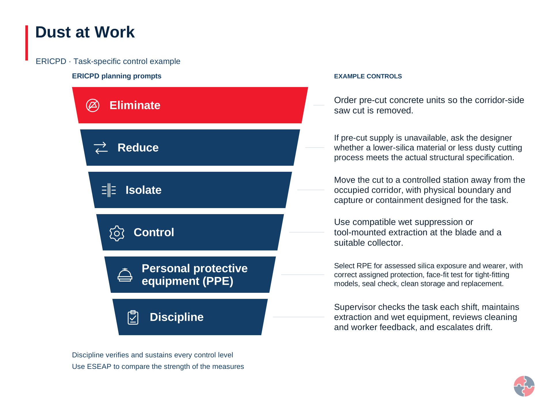
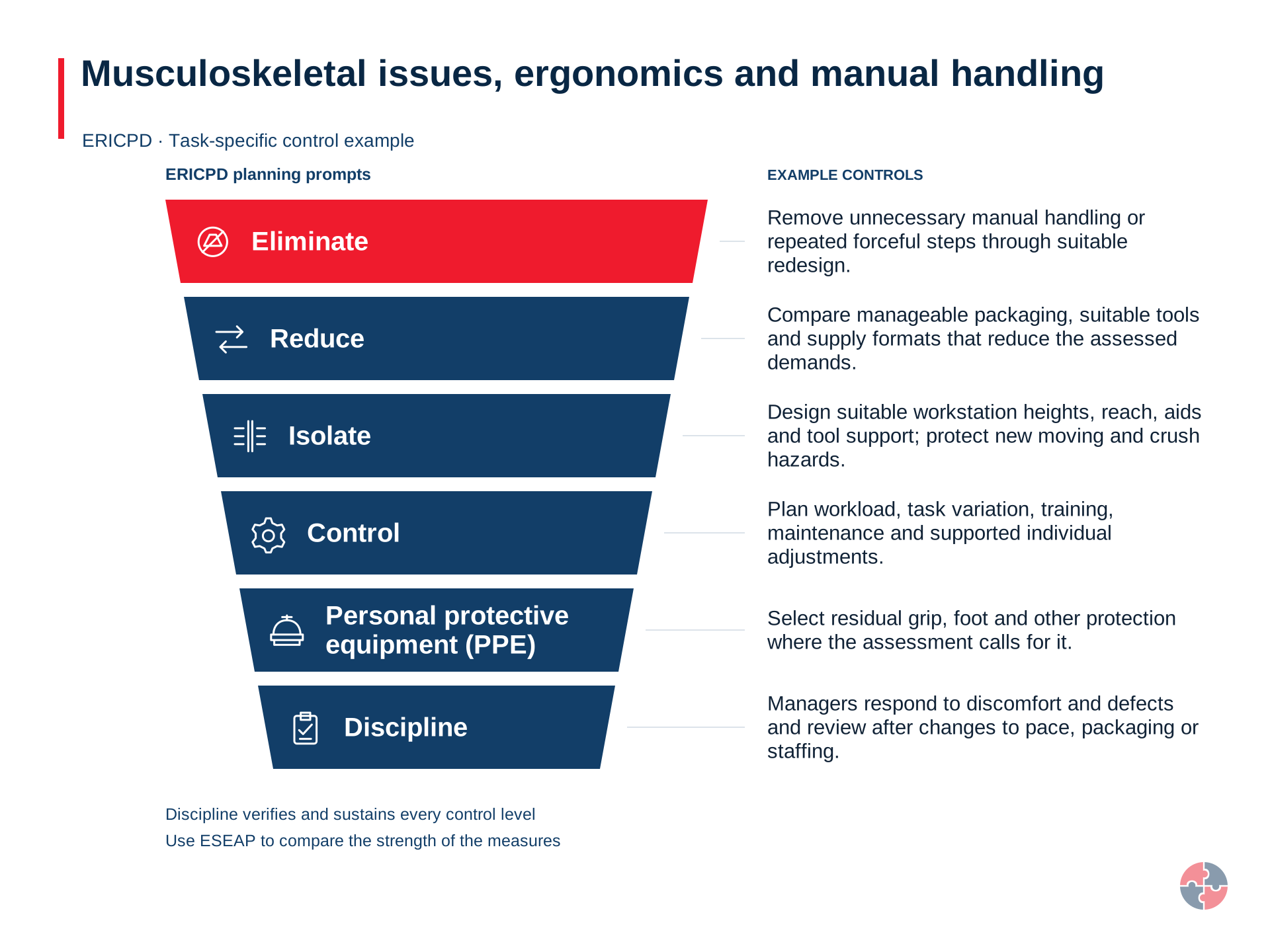
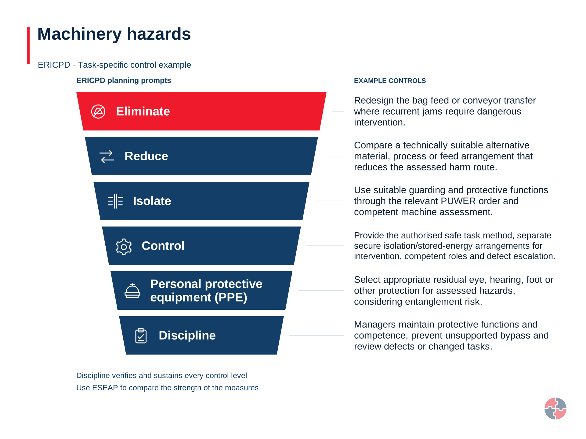
Start by avoiding the hazardous task or release, then use suitable substitution and physical controls before relying on work rules or personal protection.
The order guides a decision; the actual control depends on this task, the people exposed and what a change could introduce. A supervisor should observe the control during real work, hold a failed task and obtain a competent release after correction. HSE guidance for this control decision
Control layer
Task decision
Avoid
Avoid an emission-generating operation
Substitute or reduce
Use a lower-emission material or process where suitable
Engineer
Enclose or capture the actual plume at source
Organise and verify
Check hood position, indicators, testing and changes during real work
Protect residual exposure
Use selected and fitted RPE for assessed residual exposure
Applied case
Visible deposits have been removed, but dust still escapes at the cutting point.
Decision and explanation
The source-control and exposure pathway, even though one surface has been cleaned.
Correct decision: The source-control and exposure pathway, even though one surface has been cleaned. Assess the material, process and travel path rather than judging exposure from visible housekeeping alone.
Lesson 2
Check the complete extraction chain
Compare hood position and indicators with the current commissioned operating basis for the actual process.
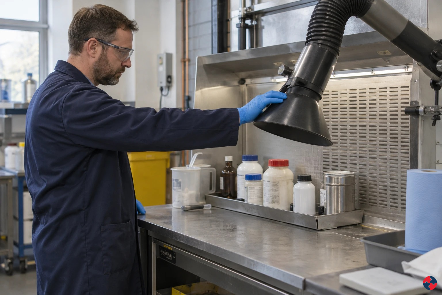
Photorealistic illustrative UK workplace scene. Review checks: Assessing: the site team identifies dust, fume, mist and vapour tasks and links each LEV asset to a COSHH assessment and health risk. Specifying: LEV purchases require task description, contaminant type, worker position, capture requirement and commissioning evidence. Implementing: Operators use hoods, on-tool extraction, booths and gauges correctly, with stop-work triggers for failed capture.
Check the complete extraction chain
An extraction fan can run while capture at the tool is ineffective. The hood must be suitable and correctly placed; air then travels through the duct and collection arrangement to a safe discharge. A fault anywhere in that chain can undermine the intended protection. The user needs a practical way to recognise that the system is operating as specified for the current task.
Use the system’s documented benchmarks, user information and suitable indicators. Do not invent a safe gauge range from a similar machine. A displaced hood and an abnormal indicator are different clues that both need attention. A recent examination report provides evidence within its scope, but it does not prove that today’s setup remains unchanged or that a new material/process has been accepted.
If an essential capture control cannot be demonstrated, hold the affected task through the assessed arrangements and report the condition. Increasing general ventilation or adding a disposable mask is not an automatic substitute for a failed engineered control. Any alternative needs its own competent assessment and authorisation.
For the exercise, trace the complete chain and assign each document or observation to the claim it supports. Identify the owner who can establish a missing baseline and the evidence needed after repair or change. Verify operation in representative use, including the hood at the tool, rather than only hearing the fan. This is a user/manager awareness check; it does not commission or design an LEV system.
What daily and routine checks should users carry out?
Routine checks catch obvious deterioration between formal tests.
Operators and supervisors are often the first line of defence. They should know how the LEV should sound, look and perform. A green test label is useful, but it is not enough if the hood is damaged, the gauge reads outside the expected range, the hose is split, the filter alarm is active or dust is escaping.
Routine checks should be specific and repeatable. The best checklist asks closed questions that produce usable data: is the airflow indicator in range, is the hood in the right position, is the duct damaged, is the filter alarm clear, is the booth door closed, is the clearance time displayed, and has the worker been observed using it correctly?
Use the indicator and hood position as a pre-use check, and compare the task with the commissioned method. HSE LEV FAQ says an airflow indicator can immediately alert users to a problem; the indicator does not replace observation of capture. A broken hose, blocked filter, alarm or visible escape means stop the dusty task and report the defect.
Check
What to look for
Action if failed
Hood position
Correct distance, angle and no obstruction.
Stop/reposition before starting task.
Airflow indicator
Gauge/manometer/tell-tale in expected range. Use an appropriate indicator with a range established during commissioning. A paper or plastic tell-tale is suitable only in very simple systems extracting low-hazard substances; it cannot be assumed suitable for other LEV.
Report and do not rely on system until checked.
Visible dust/fume/mist escape
Cloud moving away from hood or into breathing zone.
Stop and review capture, draughts and method.
Duct/hose condition
No split, crush, loose connection or blockage.
Replace/repair before use.
Filter condition/alarm
No blocked filter alarm or overloaded collector.
Change filter or call maintenance.
Booth/room condition
Doors, seals, filters, lights and pressure indicators normal.
Do not spray if booth condition is doubtful.
Correct work method
Worker not between source and hood; BA kept on when required.
Rebrief and supervise.
How can control be restored when the commissioning baseline is missing?
Separate two questions: whether exposure is adequately controlled now, and whether the evidence needed to maintain and examine the system is available. Replacing a missing sticker or copying a neighbouring machine’s report resolves neither question. A competent assessment must identify the actual system and what it is intended to control. Related guidance: Commission your LEV system.
First recover available design records, manuals, drawings, hood identities, process conditions, maintenance and examination history. Record which evidence is absent or unreliable. Give the examiner access to representative work and the people who use the system. A number without its measurement point, method, operating state and comparison basis cannot serve as a defensible performance benchmark. Related guidance: Commission your LEV system.
Where the baseline cannot be recovered, competent commissioning or recommissioning work should establish adequate control and appropriate benchmarks. Agree any interim restrictions from the actual hazard and evidence; the page gives no blanket permission to continue while paperwork is recreated. Temporary protection must itself be assessed and cannot be treated as equivalent to a failed engineering control without evidence. Related guidance: Commission your LEV system.
Recovery finishes with a tested control, usable user information, a maintenance and examination basis, and an owner who verifies those items are in use. A report marked satisfactory with unresolved capture, system-identity or compatibility questions should be challenged. Review an examination interval against the applicable legal maximum, specified-process exceptions and deterioration risk; the maximum is not a guarantee of continued effectiveness. Related guidance: Commission your LEV system.
The fan is audible but the tool hood has moved away from its normal position.
Decision and explanation
The actual capture arrangement and current operating benchmarks, not fan sound alone.
Correct decision: The actual capture arrangement and current operating benchmarks, not fan sound alone. Compare hood position and indicators with the current commissioned operating basis for the actual process.
Lesson 3
Keep swarf removal outside dangerous motion
Plan access and cleaning so enclosure and interlocks are not defeated by routine production needs.
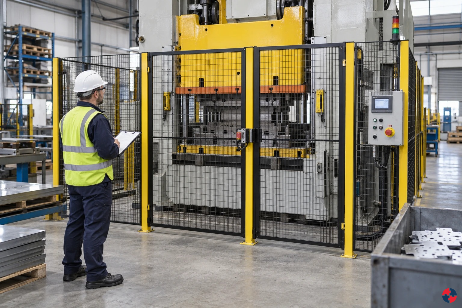
Photorealistic illustrative UK workplace scene. Review checks: Setting: Cartons jam at a packaging transfer point. Act: Stop and hold production, keep others clear and reject the tape holding the side gate. Hold / review: Hold the line: do not start or reach in while the interlock is defeated, the drive can coast into reach, the linked feed remains energised, the air pressure is uncertain, or the task differs from the agreed method.
Keep swarf removal outside dangerous motion
Swarf removal often appears to be a short supporting task. It can nevertheless place a hand or tool in the path of a rotating spindle, cutter or moving axis. An open door with machinery running is a warning about the protective boundary, not an invitation to develop a quicker manual technique. Consider ejection and unexpected movement as well as direct contact.
The safe method depends on the actual machine and task. Normal guarded operation, an operating stop and isolation for intervention are different states. A control-panel stop should not be treated as proof that every hazardous movement or energy source is prevented. The competent safe-working arrangement must define and verify the required state before access.
Raise recurring cleaning difficulties through design, maintenance and work planning. Suitable removal equipment and accessible cleaning points can reduce the need to enter the danger area. Do not normalise a bypass because it keeps production moving. An interlock is one part of the safeguarding system and needs competent restoration if defeated or faulty.
In the exercise, follow the worker’s hand from the normal operator position to the proposed clearing point. Mark where protection is lost and identify the evidence required before the task could be carried out under the approved method. Keep the learner’s decision at recognition, stopping/reporting and escalation. This course does not teach powered intervention, live adjustment or any technique for reaching around rotating equipment.
When must people stop using a machine?
Stop and keep the machine out of service when a required guard is missing or damaged, an open guard permits access to a dangerous condition, or a safeguard fails its intended function; an interlock is defeated or suspected of defeat; dangerous movement remains reachable; or isolation cannot be confirmed for an intervention. Tell the supervisor and keep others clear. A designed movable guard may open during intended safe access, but hazardous operation must remain prevented throughout that access.
Do not reach past a guard, use a spare actuator or magnet, wedge a gate, reset a fault repeatedly, or ask a colleague to watch the hazard while production continues. A fault report needs the machine identity, affected safeguard, condition found, people exposed and immediate isolation or access control. Where an injury has occurred, use the site emergency plan and obtain urgent medical help; do not move machinery or attempt a rescue unless the planned safe method and competent responders make it safe.
Only a competent authorised person may assess, repair and verify the safeguard. Restart needs a clear hand-back to the machine owner, including the original protective function and any changed operating method. HSE Introduction to machinery safety; HSE Maintenance of work equipment.
Why is an emergency stop not isolation?
An emergency stop or an open interlocked guard can stop movement without securely disconnecting energy. Before someone enters a danger zone for intervention, the planned method must prevent unexpected movement, release or reconnection, including stored energy.
Identify every energy source and connected machine. Bring equipment to the specified safe state, isolate the relevant supplies, secure against reconnection and release or restrain stored energy by the approved method. Verify that the identified hazards are controlled before access. A raised part may fall when pressure is removed: provide the designed support before the step that could let it fall. A try-start alone does not prove electrical deadness or remove gravity and pressure hazards.
Coordinate personal and group protection for everyone involved, including contractors and shift changes. Re-energise only through the agreed hand-back: account for people and tools, restore safeguards, remove locks under the authorised procedure and confirm a safe controlled restart. Electrical isolation and testing require appropriate electrical competence. Powered fault finding is an exceptional planned task for competent specialists using designed safe modes and additional protection; production staff must not improvise it. HSE Maintenance of work equipment and L22 regulation 19 explain the distinctions.
Applied case
Swarf is removed by hand through an open CNC door while the spindle turns.
Decision and explanation
Hold the unsafe intervention and obtain the approved safe access/cleaning arrangement.
Correct decision: Hold the unsafe intervention and obtain the approved safe access/cleaning arrangement. Plan access and cleaning so enclosure and interlocks are not defeated by routine production needs.
Lesson 4
Plan the reaction path of powered torque tools
Assess where tool forces can trap the operator and how the task is supported.
Related SHAREhub topic guide. Apply its prompts to the specific case below.
Plan the reaction path of powered torque tools
A powered torque tool can transmit force back into its support or the operator when a fastener resists. A reaction arm or adjacent structure can become a trapping point. Precision fastening does not make that mechanical energy harmless. Look at the tool, fastener, reaction arrangement, access position and the operator’s hands through the whole cycle.
Use suitable equipment and the manufacturer’s task information through the approved method. The reaction support needs to suit the application; a nearby surface is not automatically an acceptable stop. Keep people away from the assessed trapping path. The course does not specify torque values, fastener acceptance criteria or a method of rigging a reaction support.
A changed component position can change the hand clearance and operator reach even when the same tool is used. Review that change before proceeding. A quality requirement for a particular torque does not justify an unsafe posture or uncontrolled reaction; engineering and production need to establish a method that satisfies both requirements.
For practice, sketch the direction in which the tool or arm could move when resistance changes. Identify the physical control and the evidence that it suits this setup. Do not test a doubtful arrangement with a hand placed near the pinch point. Include a defect/reporting route and check that training reflects the actual configuration. Completion of the exercise teaches the learner to recognise the force path and request suitable assessment, not to approve a fastening operation.
Which tool fits lifting, pushing or repetition?
Use MAC for lifting/carrying/team handling, RAPP for pushing/pulling and ART for repetitive upper-limb work; each supports, rather than replaces, a suitable assessment.
HSE warns that RAPP can underestimate force and risk for small-wheeled hand pallet trucks on uneven floors or gradients. Measure the real route and complete a fuller site-specific assessment when surface, slope or force varies.
Look at the point of operation, drive and transmission parts, material paths, moving structures and unexpected movement. Trace where a hand, body or bystander could meet the hazard.
Roller nip, belt drive or rotating shaft catches clothing or a limb.
Can someone reach the nip from above, below, behind or through an opening?
Cutting, shearing or crushing
Blade, ram, closing gate or moving machine meets a person or fixed surface.
Where can the person be trapped during a cycle or unintended movement?
Ejection or impact
Tool fragment, chip, workpiece, stone or failed component leaves the machine.
Is the person protected from the full flight path and foreseeable failure?
Stored or residual energy
Coasting tool, pressure, spring, suspended part or charged circuit acts after stop.
What must be isolated, supported, cooled or dissipated before access?
Do not treat a visible emergency stop, guard or conformity mark as proof that every access and failure route has been controlled. Record the mechanism, task, credible event and exposed people before choosing measures.
The reaction arm is close to a hand after the assembly is repositioned.
Decision and explanation
The actual reaction-force, clearance and supported-work arrangement before use.
Correct decision: The actual reaction-force, clearance and supported-work arrangement before use. Assess where tool forces can trap the operator and how the task is supported.
Use the appropriate manual handling assessment
This additional teaching takes about 2–5 minutes, in addition to the course estimate. Optional reading and workplace assessment take additional time.
Start by asking whether the hazardous handling can be removed or redesigned. Where handling remains, observe the whole operation with the people who do it and choose an assessment that fits the work.
These aids support the activity assessment. Repetitive upper-limb work may need ART; variable or complex tasks may need other HSE tools or a fuller competent assessment. Mechanical lifting, stored energy, equipment safety and health decisions retain their separate controls. A low factor score, a downloaded report or completion of this course does not approve the work.
TILEO: Task, Individual, Load, Environment and Other factors. MAC: Manual Handling Assessment Charts for appropriate lifting, carrying and team handling. RAPP: Risk Assessment of Pushing and Pulling for appropriate manual pushing and pulling.
Read the portable guide to understand selection, limitations, the mixed-task example and company-branded Word/PDF records. Your existing course checks and completion requirements remain separate.
Recognise every energy source at the intervention boundary
Keep electrical, pneumatic and stored mechanical hazards within the competent isolation plan.
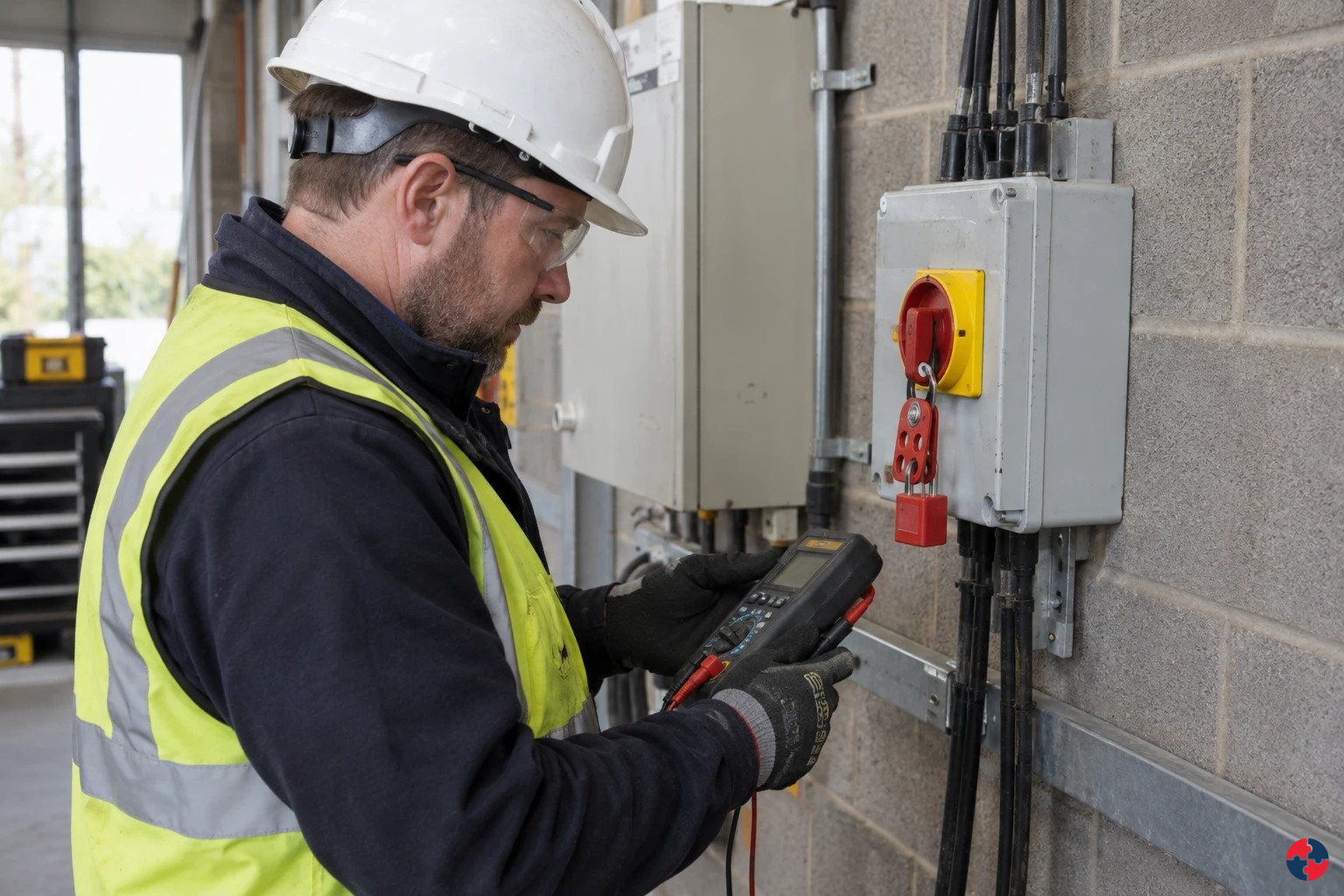
Photorealistic illustrative UK workplace scene. Review checks: Setting: the site team opens a refurbished wall where a cable route is uncertain. Act: Stop intrusive work, protect the area, identify all possible supplies and agree a revised method. Hold / review: Any unidentified conductor, unexpected voltage or changed scope stops the job.
Recognise every energy source at the intervention boundary
A local switch may control only one part of a machine. Another supply, a pneumatic connection, gravity or stored pressure can remain capable of causing injury. Start with the proposed intervention and identify the entire system boundary through the relevant competent process. Do not assume that stopping the main drive makes an adjacent fixture or actuator safe.
The safe-working arrangement must prevent dangerous energisation and deal with residual hazards for the actual task. Electrical work and verification require the appropriate competence; this awareness course does not teach live testing or isolation techniques. A tag, permit or lock is evidence of an arrangement only when it matches the actual sources and the required verified state.
Coordinate production, contractors and engineering so nobody restores a source while people remain exposed. Changes to the work scope can invalidate the original boundary. If an additional energy source is discovered, keep the work held and obtain a revised competent arrangement rather than treating it as a minor note to complete later.
For practice, use a fictional drawing with a local switch and a separate pneumatic connection. Identify the questions the task owner needs answered before access, and the information that must survive handover. Do not write operating instructions for the isolation itself. Verify the authorised handback, restored protection and readiness of affected people before the equipment returns to use. A completed maintenance task and a safe restart are separate decisions.
How should electrical isolation and proof dead be managed?
Electrical isolation should secure every source of energy, prevent re-energisation and prove the equipment dead before work starts.
Isolation is a life-saving control. The sequence should normally be: identify the equipment and supplies, switch off, isolate at a secure point, lock off, tag, prove the test device, test the circuit dead, prove the test device again and keep the isolation secure until work is complete. Where there are multiple workers, each person may need personal lock-off or a controlled group isolation system.
The isolation plan should consider alternative supplies, generators, UPS systems, solar PV, backfeeds, control circuits, stored energy, capacitors and incorrect drawings. Re-energisation should only happen after tools are removed, guards restored, people clear, permits closed and a competent person authorises hand-back.
Isolation sequence - Isolation sequence
Step
Purpose
Evidence
Identify
Confirm the correct circuit, equipment and all energy sources.
Drawing, label check and competent confirmation.
Isolate
Disconnect supply at a suitable point.
Isolation record or permit.
Secure
Prevent deliberate or accidental re-energisation.
Lock, tag and key control.
Prove tester
Confirm test equipment works before testing dead.
Test process or record.
Prove dead
Confirm the equipment is de-energised.
Permit or work-pack confirmation.
Reinstate safely
Restore only when safe and authorised.
Handover and energisation record.
At the work point, the competent worker must test the identified conductors with a suitable device, verify the device before and after the dead test, and retain control of the isolation. If the expected circuit cannot be identified or the test indicates voltage, stop and reassess rather than trying another breaker by guesswork. See HSE safe electrical work
Which assets and functions need a plan?
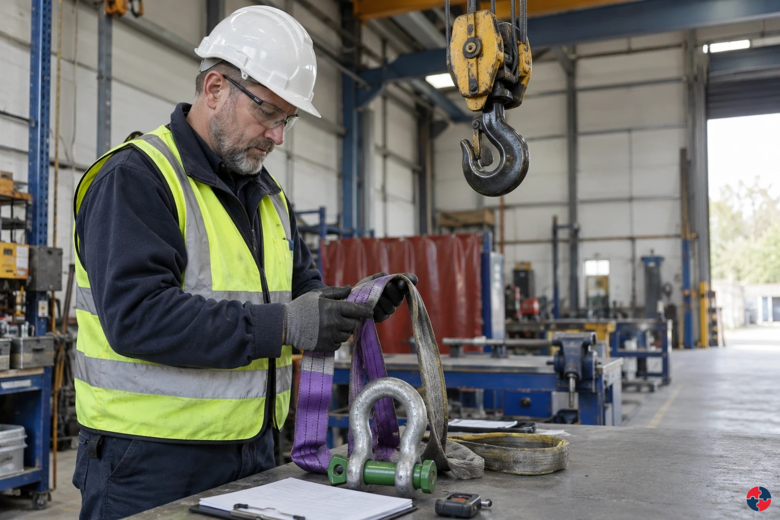
List work equipment, its tasks, safety-critical parts, degradation mechanisms and required checks. Assign an owner for each inspection, maintenance task, test and defect.
For a conveyor, include guards, interlocks, emergency stops, drives, nip points and stored energy. For mobile plant, include brakes, tyres, steering, lift functions and attachments. For a pressure system, identify whether the system qualifies for a written scheme and its protected parts. Use the manufacturer’s information and the risk assessment to define what can deteriorate and who is competent to inspect it. HSE PUWER overview and HSE inspection of work equipment.
Applied case
An additional pneumatic supply is found after electrical work has been planned.
Decision and explanation
The work remains held while the competent boundary and safe-state arrangement are reviewed.
Correct decision: The work remains held while the competent boundary and safe-state arrangement are reviewed. Keep electrical, pneumatic and stored mechanical hazards within the competent isolation plan.
Lesson 6
Treat compressed-air defects as equipment restrictions
Separate a leak observation from the competent pressure-system assessment and safe recovery.
Photorealistic illustrative UK workplace scene. Review checks: Setting: A fictional workshop receives an identified air-receiver system with connected pipework and protective devices. Act: The competent owners establish applicability and system boundary, then distinguish written scheme, examination findings and maintenance work. Hold / review: Keep affected operation held until required evidence, actions and operating acceptance are resolved; a document title alone is not release.
Treat compressed-air defects as equipment restrictions
Compressed air can store substantial energy and can move machinery or release material unexpectedly. A damaged hose or unresolved receiver defect therefore needs more than a housekeeping note. Identify the equipment, exposed people and connected tasks, and use the reporting and safe restriction arrangements for the condition.
Do not search for a leak with a hand, improvise a repair or disconnect a pressurised line. The actual depressurisation, repair and verification method belongs to competent personnel working within the assessed system. A quiet leak is not evidence of low stored energy, and a receiver’s service label cannot resolve a new defect.
The applicable pressure-equipment duties depend on the system and its scope. Inspection, maintenance and any required examination are different functions. This course supplies no universal inspection interval or acceptance criterion for a damaged component. It teaches the learner to recognise the missing evidence and preserve the restriction until the responsible assessment is complete.
In the exercise, connect the hose defect with a nearby machine that relies on pneumatic power. Decide which activities may be affected and who needs to know before any source is restored. After competent correction, verify the relevant condition, functional safeguards and handback through the actual procedure. Do not treat removal of the defect label as the verification itself. The final handover should identify what was restored, what remains restricted and who controls the next step.
How are pressure systems operated and maintained?
Operate within established safe limits using effective protective devices, competent people, clear instructions and a whole-system maintenance plan; isolate and depressurise safely before intervention.
Pressure-system examination and maintenance are different. Include corrosion, leakage, alarms, relief devices, connections, pipework, environment, change and operator handover. A pressure indication of zero at one point is not proof that all stored energy is controlled.
Start and run. Control: Limits, protection and competent operation.; Stop: Unreliable reading or excursion.
Maintain. Control: Isolation, depressurisation, verification and safe access.; Stop: Trapped pressure or unknown connection.
What happens after pressure-system repair or modification?
Hold the affected system, assess the change against design and safe limits, update the written scheme when required, obtain competent examination where the scheme or law requires it, and release only after controlled testing and named acceptance.
Repairs, replacement components, changed fluids and operating conditions can alter the pressure boundary. A maintenance completion or leak test alone is not statutory examination or authority to operate.
Repair or replacement. Check: Material, design, protective devices and required examination.; Release condition: Competent evidence accepted.
Changed duty. Check: Safe limits, scheme scope and instructions.; Release condition: Updated and approved basis.
What should happen after a pressure release or alarm?
Move people clear, raise the alarm, follow the site emergency plan and keep the system isolated from further operation; do not approach a leak, adjust a relief device or reopen a vessel until the hazard and safe state are established by authorised people.
Treat vessel, line and connected process as potentially energised. Investigate cause and affected scope, protect others, obtain any required competent examination and controlled test, then require named operating acceptance.
Leak or unusual sound. Immediate action: Withdraw and warn.; Restart barrier: No approach until assessed.
Relief device operates. Immediate action: Escalate and preserve evidence.; Restart barrier: No reset-only return.
Rupture or injury. Immediate action: Emergency response and exclusion.; Restart barrier: Investigation and competent release.
Report and classify the defect, keep dangerous equipment out of use, repair competently and prove the affected function before release.
A missing guard, failed brake, cracked lifting part or uncertain pressure protection needs a clear stop-use decision. Tagging helps communicate a hold but does not physically prevent reuse on its own; choose isolation or access control as needed. Record who may remove the hold and what evidence they require. Repeated defects call for cause investigation and a changed plan. HSE maintenance of work equipment and HSE thorough examination of lifting equipment.
Separate a service defect from an examination report
An ordinary service defect is recorded, quarantined and resolved through the equipment system. A statutory examiner’s finding follows its own report route as well as the work restriction. For GB LOLER, the examiner immediately informs the dutyholder of dangerous defects; serious existing or potential dangerous defects require the prescribed written report and a copy to the enforcing authority as soon as practicable. Respect any specified remedy deadline and prohibition on continued use. HSE: lifting examinations and dangerous-defect reports.
For GB PSSR, the competent person’s imminent-danger process includes immediate notification, a written report to the user/owner and a copy to the enforcing authority within 14 days; prevent operation until the required remedy is made. HSE: pressure systems. NI has separate LOLER/PSSR instruments and enforcing routes: apply the corresponding current provisions and competent advice. A manager cannot waive an examiner’s restriction; not every minor maintenance defect is externally reportable.
Applied case
A leaking hose is replaced, but the receiver’s recorded defect remains unresolved.
Decision and explanation
Only the hose action is complete; the receiver and affected system restrictions need their own evidence.
Correct decision: Only the hose action is complete; the receiver and affected system restrictions need their own evidence. Separate a leak observation from the competent pressure-system assessment and safe recovery.
Lesson 7
Composite dust at trimming and sanding
Stop dusty work when the material hazard or effective capture is unresolved.
Related SHAREhub topic guide. Apply its prompts to the specific case below.
Understand the activity and how harm develops
Trimming breaks the finished material into particles of different sizes. The most visible dust is not necessarily the fraction reaching deep into the lungs. Nearby workers and people cleaning the area may be exposed even if they never operate the cutter.
Identify the material and its machining information before deciding the controls. Carbon fibre, glass fibre and different resin or filler systems are not interchangeable hazards. Do not assume every composite contains silica, or that every dust has the same fire and explosion behaviour.
Reduce dust generation, enclose the source and capture emissions where produced. Clean using an assessed method rather than dry sweeping or compressed-air blowing. Review exposure during tool changes, finishing and collector emptying as well as steady cutting, and arrange suitable health surveillance where indicated.
Recognise the evidence boundary
Question
Case evidence
What is observed?
Fine dust escapes from an open composite-trimming task and settles on nearby surfaces.
How can harm occur?
Workers may inhale hazardous particles or suffer skin and eye irritation.
What information is needed?
Match the assessment to the actual composite and cutting process.
Protect, manage and verify
Purpose
Practical application
Immediate protection
Enclose cutting and provide effective source extraction.
Accountable work arrangement
Assess the actual composite. Reduce and enclose dust generation. Capture at the source. Control cleaning and collector exposure.
Release verification
Confirm cleaning and waste handling do not re-suspend dust.
Apply this at work
Stop dusty work when the material hazard or effective capture is unresolved.
Why does particle size matter?
Particle size determines where dust deposits in the body and what kind of harm it can cause.
Inhalable dust is the fraction that can enter the nose and mouth during breathing. It may deposit in the nose, throat and upper airways, causing irritation, rhinitis, dermatitis after contact, or diseases such as nasal cancer from some hardwood dusts.
Respirable dust is smaller and more dangerous for many lung diseases because it can travel deep into the alveoli. Respirable crystalline silica is a classic example: it can cause silicosis, lung cancer and COPD even when the dust cloud is not obvious.
Dust may also be thoracic, fibrous, ultrafine or biologically active. The practical lesson is simple: do not judge risk by how visible the dust looks. Use the material data, task evidence, exposure monitoring and professional judgement. See HSE - Dust in the workplace: General principles of protection.
Dust fractions and health relevance - Dust fractions and health relevance
The floor is clean but a fine cloud follows the cutter.
Decision and explanation
Stop and restore effective capture at the source.
Housekeeping does not control the cloud being breathed now. Sweeping can re-suspend particles and misses source control. Curing does not remove every machining exposure hazard.
Lesson 8
LEV capture and dust collection
Stop the emitting task when extraction is faulty or outside its validated operating condition.
Photorealistic illustrative UK workplace scene. Review checks: Assessing: the site team identifies dust, fume, mist and vapour tasks and links each LEV asset to a COSHH assessment and health risk. Specifying: LEV purchases require task description, contaminant type, worker position, capture requirement and commissioning evidence. Implementing: Operators use hoods, on-tool extraction, booths and gauges correctly, with stop-work triggers for failed capture.
Understand the activity and how harm develops
Follow dust from the cutting edge through the hood, duct, collector, fan and discharge. A running motor proves movement somewhere in the system, not enough capture at the tool. A damaged hose, blocked filter or poorly positioned hood can defeat the control.
Use the commissioned benchmark for this task and system. Extra bends, long hoses or added branches change resistance and can reduce performance, but appearance alone cannot quantify the result. Collector and discharge arrangements must address the actual dust and any assessed fire or explosion properties.
Keep the source inside the effective capture region and avoid placing the worker between source and hood. Check indicators before use, investigate deviations and maintain examination records. Empty or change collection containers through the assessed method without creating a second exposure event.
Recognise the evidence boundary
Question
Case evidence
What is observed?
The on-tool hood is displaced and the collector indicator is outside its normal benchmark.
How can harm occur?
Dust escapes into the breathing zone or leaks during collection and disposal.
What information is needed?
Compare the indicator with the system’s valid commissioned range.
Protect, manage and verify
Purpose
Practical application
Immediate protection
Provide commissioned capture, collection and safe discharge.
Accountable work arrangement
Keep capture at the emission point. Check commissioned performance benchmarks. Maintain the complete extraction system. Control collector emptying and changes.
Release verification
Verify collector integrity and safe waste removal after maintenance.
Apply this at work
Stop the emitting task when extraction is faulty or outside its validated operating condition.
What parts make up an LEV system?
A complete LEV system is an airflow chain; weakness in one part weakens the whole control.
The visible hood is only the beginning. The system includes ducts, bends, dampers, air cleaners, filters, fans, stacks, make-up air and monitoring devices. It may also include the machine guard, spray booth structure, interlocks, pressure indicators, filter alarms, airflow gauges and operating method.
A professional review follows the air path from contaminant source to safe discharge. It asks whether enough air reaches the hood, whether the duct carries contaminant without settling, whether the filter or collector is suitable, whether the fan can overcome system resistance, and whether discharge could expose other people or re-enter the building.
Component
Purpose
Common failure
Hood or enclosure
Captures or contains contaminant.
Too far away, wrong shape, damaged, obstructed or poorly used.
Ductwork
Carries contaminated air away.
Leaks, blockages, crushed flexible duct or poor bends.
Air cleaner/filter
Removes particles, mist or vapour where needed.
Blocked filters, wrong media or poor disposal of waste.
Fan/air mover
Creates airflow through the system.
Wrong rotation, worn fan, belt slip or insufficient duty.
Discharge
Releases air safely.
Discharge near doors, windows, intakes or occupied areas.
Make-up air
Replaces extracted air.
Room becomes starved, draughty or process airflow is disrupted.
Indicator/instrument
Shows whether performance is within expected range.
Gauge absent, ignored, uncalibrated or not understood.
Applied case
The fan sounds normal but the hood no longer captures dust.
Decision and explanation
Stop the task and investigate against the commissioned criteria.
That may expose others and leave the source uncontrolled. A change can increase resistance and worsen the problem. Sound is not a capture-performance measurement.
Lesson 9
Rotating tools, CNC enclosure and swarf
Stop work for an open, defeated or faulty guard protecting moving machinery.
Photorealistic illustrative UK workplace scene. Review checks: Setting: Cartons jam at a packaging transfer point. Act: Stop and hold production, keep others clear and reject the tape holding the side gate. Hold / review: Hold the line: do not start or reach in while the interlock is defeated, the drive can coast into reach, the linked feed remains energised, the air pressure is uncertain, or the task differs from the agreed method.
Understand the activity and how harm develops
Rotating cutters can catch clothing, hair or gloves and draw a person in faster than they can react. A small tool is still dangerous, and a slowing spindle may retain enough energy to injure. Sharp swarf adds a separate handling hazard.
The enclosure controls access and ejection only when it is complete and its protective functions work. Do not defeat the door system to improve visibility or speed a task. Workholding, cutter selection and parameters must suit the actual part and process.
Arrange cleaning and tool changes with the machine in the required safe state. Use purpose-suited tools for swarf removal after isolation or the validated safe method, not fingers near live rotation. Controlled restart includes checking guards, workholding and the absence of tools or people in the enclosure.
Recognise the evidence boundary
Question
Case evidence
What is observed?
A CNC door is open while the spindle runs and swarf is being removed by hand.
How can harm occur?
Entanglement, ejected fragments and sharp swarf can cause severe injury.
What information is needed?
Check the enclosure and protective functions before production.
Protect, manage and verify
Purpose
Practical application
Immediate protection
Maintain guarding, interlocks and secure workholding.
Accountable work arrangement
Keep the enclosure effective. Secure workholding and cutters. Use approved clearing and isolation. Keep hands from rotating parts.
Release verification
Confirm swarf clearing occurs only under the approved safe method.
Apply this at work
Stop work for an open, defeated or faulty guard protecting moving machinery.
How does an unguarded machine injure people?
Hazardous motion reaches a person when a hand, clothing or body can enter a nip, cutting path, closing gap or moving enclosure before the machine reaches a safe state. The immediate harm can be entanglement, crushing, amputation, laceration or impact; survivors may have lasting disability.
A rotating roller grips clothing or a hand and draws the limb into a narrowing gap. A ram or gate closes on a person and compresses tissue against a fixed surface. A blade cuts on contact; a broken tool or workpiece can strike the eye or body. Unexpected restart or stored pressure can create the same contact while someone is clearing a jam. Speed, mass, force, coast-down time, reach distance, poor visibility, bypassed guards and linked equipment change the chance and severity. HSE Introduction to machinery safety; HSE hierarchy of controls.
Machinery harm mechanisms and stop signs
Task or exposure
Route and likely harm
Early sign and stop point
Feeding rollers or conveyors
An in-running nip draws clothing, hair or a hand into moving surfaces; crush injury, fracture, degloving or amputation can follow.
Guard gap, reachable nip, loose clothing near motion or repeated snagging: stop use and prevent access.
Power press, mixer or driven gate
A moving part closes against another surface or unexpectedly restarts; crushing, shearing or entrapment may cause major injury or death.
Gate can open while motion remains, unexpected reset, person able to remain inside or changed stopping time: hold use.
Saw, cutter or ejected workpiece
Contact cuts or severs tissue; fragments can penetrate an eye or strike a person.
Missing blade guard, damaged enclosure, altered feed or unexpected ejection: stop and investigate.
Jam clearing or maintenance
Stored pneumatic, hydraulic or gravitational energy or linked machinery moves after a motor stop; hands or whole body can be trapped.
Unknown energy state, no personal control of isolation, coasting or a changed jam: withdraw and seek competent help.
These are primarily acute injury mechanisms. Long-term loss of function or disability can follow severe injury; this page does not imply a separate chronic exposure limit for guarding. Machine-specific injury patterns still require the actual risk assessment. HSE explains the machine hazard and safeguard route in Official guidance.
Applied case
A string of swarf wraps around the rotating cutter.
Decision and explanation
Stop and follow the authorised clearing and isolation method.
An improvised tool does not establish safe separation. The swarf must be dealt with in a verified safe state. Gloves can be caught with the swarf.
Lesson 10
Powered torque tools and reaction forces
Stop when the reaction support, engagement or hand clearance is uncertain.
Related SHAREhub topic guide. Apply its prompts to the specific case below.
Understand the activity and how harm develops
The reaction arm transfers torque into a suitable point on the assembly or fixture. If it contacts an unsuitable edge, slips or closes onto a hand, the tool can move abruptly. A calibration certificate concerns measurement accuracy, not the safety of the reaction arrangement.
Use the approved tool, socket and reaction method for this joint. Consider access, posture, stable support and the sequence of tightening. Keep hands outside reaction gaps and do not improvise a longer handle or a different reaction point to reach an awkward fastener.
Check condition before use and investigate unusual movement or vibration. Plan repeated work using real task exposure and maintain tools. The product’s fastening specification and the operator’s safety controls both need to be satisfied before the joint is accepted.
Recognise the evidence boundary
Question
Case evidence
What is observed?
A powered torque tool’s reaction arm is close to the operator’s hand.
How can harm occur?
Reaction movement can crush fingers or twist the wrist; repeated use may add vibration exposure.
What information is needed?
Check the tool and reaction point against the approved task.
Protect, manage and verify
Purpose
Practical application
Immediate protection
Provide compatible reaction fixtures and secure tool engagement.
Accountable work arrangement
Use the approved reaction point. Check tool engagement and condition. Keep hands clear of reaction gaps. Review repeated exposure and abnormal movement.
Release verification
Confirm abnormal movement leads to investigation rather than repeated attempts.
Apply this at work
Stop when the reaction support, engagement or hand clearance is uncertain.
Which mechanical mechanisms should you look for?
Look at the point of operation, drive and transmission parts, material paths, moving structures and unexpected movement. Trace where a hand, body or bystander could meet the hazard.
Roller nip, belt drive or rotating shaft catches clothing or a limb.
Can someone reach the nip from above, below, behind or through an opening?
Cutting, shearing or crushing
Blade, ram, closing gate or moving machine meets a person or fixed surface.
Where can the person be trapped during a cycle or unintended movement?
Ejection or impact
Tool fragment, chip, workpiece, stone or failed component leaves the machine.
Is the person protected from the full flight path and foreseeable failure?
Stored or residual energy
Coasting tool, pressure, spring, suspended part or charged circuit acts after stop.
What must be isolated, supported, cooled or dissipated before access?
Do not treat a visible emergency stop, guard or conformity mark as proof that every access and failure route has been controlled. Record the mechanism, task, credible event and exposed people before choosing measures.
The reaction arm will close against the operator’s fingers.
Decision and explanation
Reposition using the approved safe reaction arrangement before energising.
Hand clearance must exist before force is applied. Gloves cannot prevent crushing in the reaction gap. An improvised reaction point may fail or damage the assembly.
Lesson 11
Electrical and stored-energy isolation
Stop if any energy source, isolation boundary or verification is uncertain.
Teaching graphic from the linked SHAREhub source section.
Understand the activity and how harm develops
The maintenance boundary can include electrical feeds, stored charge, pressure, gravity and process materials. A label on one switch does not prove which equipment it controls, and a remote or secondary supply may bypass the obvious isolation point.
Competent personnel identify the equipment and use the approved isolation and proving method. Electrical testing requires suitable instruments and competence; learners should not treat a simulation as instructions for live work. Stored energy and parts capable of falling need separate control.
Coordinate multiple workers and contractors so no one can restore energy while another remains exposed. Record changes to the scope and complete controlled handback, including guards and protective functions. A permit records the arrangement; it cannot make an incorrect isolation physically effective.
Recognise the evidence boundary
Question
Case evidence
What is observed?
An electrician has isolated a local switch but another supply and a pneumatic circuit remain connected.
How can harm occur?
Unexpected energisation, electric shock or movement can injure the maintenance team.
What information is needed?
Match equipment identity and every supply to the isolation plan.
Protect, manage and verify
Purpose
Practical application
Immediate protection
Provide identifiable secure isolation and designed stored-energy controls.
Accountable work arrangement
Identify all energy sources. Secure and verify isolation. Control residual energy and movement. Coordinate workers and handback.
Release verification
Confirm all people and affected systems are accounted for before restoration.
Apply this at work
Stop if any energy source, isolation boundary or verification is uncertain.
What electrical control sequence prevents exposure?
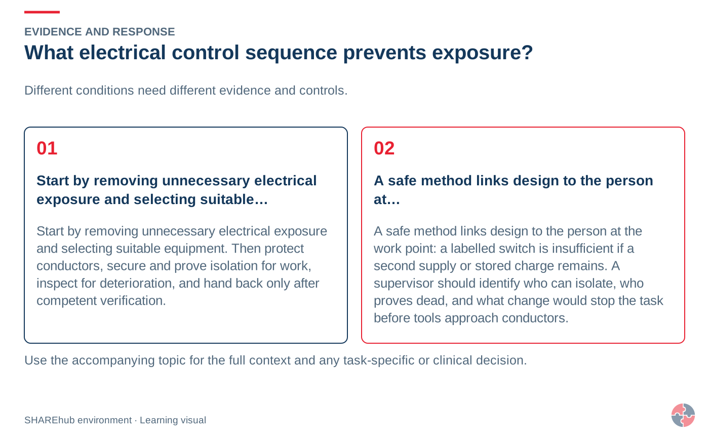
Start by removing unnecessary electrical exposure and selecting suitable equipment. Then protect conductors, secure and prove isolation for work, inspect for deterioration, and hand back only after competent verification.
Best-practice guide · six simple steps
Best-practice guide: Electrical control measures, safe systems and inspection
Start with the key actions, then explore value, a workplace example, harm, stronger controls and further help. Choose a step or use Previous and Next; the guide does not advance automatically.
Keep one card or the full set for social sharing, team briefings and learning. Each PDF contains one card per page. Read the full topic for explanations, questions and source links.
Read all six steps as text
1. What electrical control sequence prevents exposure?
Start by removing unnecessary electrical exposure and selecting suitable equipment.
Avoid / redesign: Use external diagnostics or remove the faulty equipment from use where that avoids exposed electrical work.
Control the task: Securely isolate relevant supplies, prevent reconnection and prove dead using the approved safe-isolation method.
Verify before release: If the hazardous step remains, keep it within the task assessment and select the stronger feasible remaining controls.
Start by removing unnecessary electrical exposure and selecting suitable equipment. Then protect conductors, secure and prove isolation for work, inspect for deterioration, and hand back only after competent verification. Electrical safety depends on suitable design, protection, secure isolation and inspection that finds defects before people are exposed.
Apply it: Which part of this plan would you check at the workface before authorising the task?
2. Turn electrical control measures, safe systems and inspection knowledge into a decision
Use the evidence to improve the actual work arrangement.
Change at source: Use external diagnostics or remove the faulty equipment from use where that avoids exposed electrical work.
Make it observable: If the hazardous step remains, keep it within the task assessment and select the stronger feasible remaining controls.
Keep useful evidence: Revised work pack, isolation and test record, briefing, certificate and defect closure.
Electrical safety depends on suitable design, protection, secure isolation and inspection that finds defects before people are exposed. A damaged conductor, failed protective device or unexpected supply can cause shock, arc injury or fire even where a test label is current. Revised work pack, isolation and test record, briefing, certificate and defect closure.
Apply it: What evidence would show that the change improves this task, rather than only completing a record?
Fictional example: a practical application of the existing topic lesson.
Setting: the site team opens a refurbished wall where a cable route is uncertain.
Act: Stop intrusive work, protect the area, identify all possible supplies and agree a revised method.
Hold / review: Any unidentified conductor, unexpected voltage or changed scope stops the job.
Competent lead locates, isolates and proves the circuit dead at the work point; supervisor keeps other trades clear. Restore guards and supply only after people clear; give the client an updated circuit record.
Apply it: At which point would you hold this example, and what evidence would allow it to proceed?
Connect the task, the route to the person and the control that can fail.
Electric shock: Current passes through the body after contact with live parts.
Electrical burns: Current heats tissue or arc energy burns skin and eyes.
Loss of muscle control: Shock causes spasm, inability to let go or a fall.
Electric shock: Current passes through the body after contact with live parts. Electrical burns: Current heats tissue or arc energy burns skin and eyes. Loss of muscle control: Shock causes spasm, inability to let go or a fall.
Apply it: Who could be exposed, including other trades, cleaners, maintainers and people nearby?
5. Choose controls for electrical control measures, safe systems and inspection
Start with the stronger practicable options and verify their effect.
Elimination: Use external diagnostics or remove the faulty equipment from use where that avoids exposed electrical work.
Engineering controls: Use a suitable off-line test or replaceable module where it safely proves the fault without exposed live conductors.
Engineering controls: Securely isolate relevant supplies, prevent reconnection and prove dead using the approved safe-isolation method.
Engineering controls: Provide suitable enclosures, protective devices and test equipment for the actual circuit and installation.
Administrative controls: Confirm circuit identity, competence, test scope and restart authority; separately justify and control any unavoidable energised test.
Elimination: Use external diagnostics or remove the faulty equipment from use where that avoids exposed electrical work. Engineering controls: Use a suitable off-line test or replaceable module where it safely proves the fault without exposed live conductors. Engineering controls: Securely isolate relevant supplies, prevent reconnection and prove dead using the approved safe-isolation method. Engineering controls: Provide suitable enclosures, protective devices and test equipment for the actual circuit and installation. Administrative controls: Confirm circuit identity, competence, test scope and restart authority; separately justify and control any unavoidable energised test. Read the full control table for qualifications, ownership and verification. Use the actual task and applicable jurisdiction; existing technical approval remains unchanged.
Apply it: Which stronger option can be used here, and who will verify it before accepting the remaining risk?
6. Use the full electrical control measures, safe systems and inspection lesson
Follow the official sources below and retain the task-specific evidence.
Official guidance: HSE - Introduction to electrical safety
Official guidance: HSE - Electricity at work: safe working practices HSG85
Task decision: Revised work pack, isolation and test record, briefing, certificate and defect closure.
Use the full topic for the decision points, practical examples, detailed control tables and source scope. HSE guidance applies to Great Britain; use HSENI for the Northern Ireland route and the source’s stated jurisdiction. A simplified guide does not change the page’s technical-review or approval status.
Apply it: Which official source and full-topic section will you use to resolve the next decision?
Simplified learning guide. Use the full topic, current official guidance and the actual work arrangements. Workplace scenarios labelled fictional are illustrative examples.
A safe method links design to the person at the work point: a labelled switch is insufficient if a second supply or stored charge remains. A supervisor should identify who can isolate, who proves dead, and what change would stop the task before tools approach conductors.
Applied case
The local switch is off but the drawing shows a second feed.
Decision and explanation
Resolve and secure the complete isolation before work.
Its effect on the equipment remains uncertain. Paperwork cannot disconnect or prove an electrical supply. The work boundary includes every relevant supply.
Lesson 12
Compressed air, pressure plant and leaks
Do not use or work on a defective pressurised system without approved isolation and control.
Teaching graphic from the linked SHAREhub source section.
Understand the activity and how harm develops
The receiver, pipework and protective devices form a system. A small opening can release energy rapidly, while a failed hose can move violently. Blowing compressed air at skin or clothing can injure people and spread contamination into the breathing zone.
Identify applicable pressure-system duties, safe operating limits and the required written scheme and examinations. Servicing the compressor is not the same as examining the pressure system. A gauge reading inside a normal band does not resolve corrosion, damaged hose or a protective-device defect.
Remove defective equipment from use through the approved isolation method. Use compatible rated components and competent repair, then verify the system before release. A leak should not be located with bare hands or repaired while the relevant section remains pressurised.
Recognise the evidence boundary
Question
Case evidence
What is observed?
An air receiver has an unresolved defect and a damaged hose leaks beside the maintenance route.
How can harm occur?
Stored pressure can cause hose whip, injection injury or equipment rupture.
What information is needed?
Identify the receiver and its applicable examination requirements.
Protect, manage and verify
Purpose
Practical application
Immediate protection
Provide sound rated pipework, hose restraints where assessed and protective devices.
Accountable work arrangement
Remove defective pressure equipment. Maintain protective devices and rated components. Complete applicable examination actions. Isolate before competent repair.
Release verification
Confirm safe isolation and competent release after repair.
Apply this at work
Do not use or work on a defective pressurised system without approved isolation and control.
How do PUWER, LOLER and pressure-system law fit together?
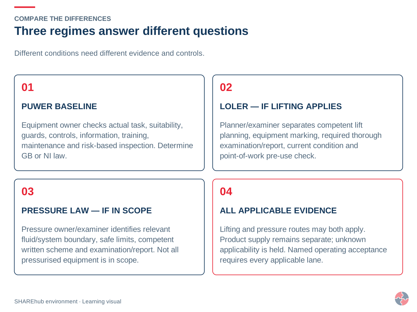
Use PUWER for the general safe-use duties of work equipment; add Lifting Operations and Lifting Equipment Regulations (LOLER) when the activity and equipment are within lifting law, and add Pressure Systems Safety Regulations (PSSR) where the pressure-system definition and application provisions are met. One asset can trigger more than one regime.
Do not infer that every pressure vessel needs a written scheme or that every vertical movement is LOLER lifting. Decide jurisdiction, equipment identity, use, relevant fluid, load and exceptions with competent evidence before choosing the route. Product-supply law is a separate question.
Question
Route
Evidence
Is equipment used at work?
GB or NI PUWER baseline.
Task and equipment assessment.
Does it lift or lower a load?
GB or NI LOLER applicability review.
Lift plan, marking and examination evidence.
Does it meet pressure-system scope?
GB PSSR 2000 or NI PSSR 2004 applicability review.
System boundary, fluid, limits and written scheme decision.
Is it being placed on a market?
Current sector product-supply law.
Conformity evidence, separate from workplace acceptance.
The compressor was serviced but a receiver action remains open.
Decision and explanation
Only after the required defect action and release are resolved.
Tape is not a competent pressure-system repair. Servicing does not replace the pressure-system examination decision. An invented limit does not establish integrity.
Lesson 13
Restore the machining control chain before production resumes
Coordinate dust capture, guarding and energy-state evidence without substituting one control for another.
Photorealistic illustrative UK workplace scene. Review checks: Assessing: the site team identifies dust, fume, mist and vapour tasks and links each LEV asset to a COSHH assessment and health risk. Specifying: LEV purchases require task description, contaminant type, worker position, capture requirement and commissioning evidence. Implementing: Operators use hoods, on-tool extraction, booths and gauges correctly, with stop-work triggers for failed capture.
Restore the machining control chain before production resumes
In this additional fictional case, a machining cell has been moved to accommodate a different component. The tool hood no longer sits at its established position, and dust is visible beyond the enclosure. The collection fan runs. During a production pause, a worker proposes clearing swarf through the open door. The fastening station’s reaction arm now sits beside a hand position. Engineering identifies an additional pneumatic supply and an outstanding receiver defect.
Begin by protecting the affected work through the site arrangements. Do not infer that the fan sound proves capture, that a stopped program proves safe access or that a torque setting resolves the reaction-force geometry. Each is a separate control claim. Record the current restrictions and communicate them to production, engineering and anybody who could restore energy or enter the area.
Review the change as implemented. The actual material, task and enclosure arrangement must connect to the extraction system’s operating basis. A satisfactory earlier report does not automatically accept the moved hood or changed process. Establish the correct benchmark and competent verification route. Do not use the course to invent an airflow range or exposure concentration.
For intervention, obtain the approved safe method and verified boundary covering all relevant energy and material hazards. An open CNC door or local switch is not proof of that state. Keep the reaction-arm trapping concern within the task review rather than asking the operator to be more careful. The receiver’s unresolved defect remains a separate system concern even if the visible hose is repaired.
Restart requires evidence that the current arrangement is suitable, safeguards work and responsibilities have been handed back. Preserve the independent lesson decision: a learner can recognise and report the problem without being authorised to commission extraction, perform electrical tests or approve the pressure equipment. Do not replace an engineering hold with additional PPE unless a competent assessed alternative has actually been established.
Use a fictional control-chain table with source capture, dangerous motion, tool reaction and energy/pressure rows. For each, list the observation, the document or check still required, the competent owner and the stop/restart condition. A single overall green status is not enough when the underlying evidence differs. Retain valid records within their scope and identify the specific changed condition they no longer establish.
What happens when a new workpiece changes the capture conditions?
A normal indicator reading describes one measured condition, not every possible use of the system. A changed workpiece, emission direction, operator position or simultaneous hood use can defeat capture even where the fan runs and a familiar gauge remains in range. Screen changes before using the new process as routine work. Related guidance: Commission your LEV system.
In an illustrative fabrication workshop, a bench extraction hood was commissioned for a small component held inside its defined working zone. A larger component requires the operator to stand between the emission and hood and rotate the piece during finishing. The supervisor holds the changed operation. The old commissioning report remains valuable evidence of the previous configuration, but it does not establish control of the new one. Related guidance: Commission your LEV system.
The process owner and competent LEV specialist establish the substances, emissions, work rate, operator movements and simultaneous demands. They consider source reduction and improved enclosure or task layout before treating greater fan output as the answer. Any change to ducts, fan, filtration or discharge needs assessment of system balance, contaminant compatibility and fire/explosion or re-entry consequences where relevant. Related guidance: Commission your LEV system.
The acceptance test represents the intended operation and relevant adverse conditions. It observes capture or containment and compares defined technical measurements with the appropriate design and commissioning benchmarks. Where the hazard or uncertainty calls for it, competent exposure assessment supports the decision. A visually clear room or one airflow number cannot alone establish adequate control of an invisible harmful contaminant. Related guidance: Commission your LEV system.
Before release, provide a comprehensible record of the authorised process/configuration, hood use, indicators and action limits, restrictions, maintenance and user instruction. The operator demonstrates the new working zone and a stop when the arrangement cannot be maintained. Update the schematic, manual, logbook and future examination basis; retain the earlier configuration history so later changes can be traced. Related guidance: Commission your LEV system.
Use a machine only when the task is authorised, its safeguards are effective and the operator knows how to stop and report a problem. Stop when a protection measure is missing, defeated, damaged or unreliable; keep the equipment out of use until competent assessment and release.
Before starting
Confirm the machine, material, operating mode and surroundings match the assessed task. Check guards and fixings, clear space and access routes, workpiece support, extraction where required and the status of maintenance or isolation. Carry out only the functional checks defined by the manufacturer and local safe procedure, from a protected position. Never test a safeguard with a hand or other body part in danger. Confirm required inspections and the operator’s task-specific instruction.
During the task
Keep guards in place and use the intended feeding equipment. Watch for repeated jams, changed stopping behaviour, unusual movement, damaged controls or people entering the area. Do not hold an interlock defeated, bridge a device or improvise access to meet production targets. Repeated nuisance trips need investigation of the task and machine design, not removal of protection.
Stopping and handover
Use the planned stopping procedure. For cleaning, adjustment or entry into danger, follow the machine-specific isolation method. Report defects precisely, identify the machine and safeguard, and prevent unauthorised reuse. A shift handover must identify incomplete work, changed settings and any restriction still in force. HSE PUWER overview and HSE Inspection of work equipment support these checks.
How should a safety function be tested?
Specify the function, safe test position, expected response, acceptance criteria and restoration before a competent person tests it.
For an interlock, confirm the guard state, stopped or prevented motion, run-down and restart behaviour for the real access route. A green indicator alone is not proof. Test from a protected position and record failures; do not put a person in danger to demonstrate the function. After repair or modification, consider the whole linked system, not only the replaced component. HSE L22 Safe use of work equipment and HSE maintenance of work equipment.
Applied case
A moved machining cell combines poor capture, unsafe clearing, a new reaction pinch point and unresolved energy/pressure evidence.
Decision and explanation
Verify each changed control and the competent handback while maintaining unresolved restrictions.
Correct decision: Verify each changed control and the competent handback while maintaining unresolved restrictions. Coordinate dust capture, guarding and energy-state evidence without substituting one control for another.
Lesson 14
Take a verified action into the workplace
Connect one actual task to an owner, evidence and a clear release or escalation decision.
Photorealistic illustrative UK workplace scene. Review checks: Assessing: the site team identifies dust, fume, mist and vapour tasks and links each LEV asset to a COSHH assessment and health risk. Specifying: LEV purchases require task description, contaminant type, worker position, capture requirement and commissioning evidence. Implementing: Operators use hoods, on-tool extraction, booths and gauges correctly, with stop-work triggers for failed capture.
Turn awareness into a practical question
Awareness in an original fictional aerospace manufacturing and airport-interface site. GB occupational guidance has separate NI routes; environmental duties depend on the UK nation and permit. This course does not confer engineering, aircraft maintenance, product-release, lifting, rescue, driving or airside authorisation.
Choose one relevant operation from the course. Describe the person or environment at risk, the mechanism of harm and the exact condition that needs controlling. Separate an observation from a conclusion. A display, signature, badge or clean appearance answers only a limited question.
Use the included practice resources to prepare a fictional task brief, risk review or verification question. Decide which competent role owns the decision and which evidence must be available before work restarts or work is released. Keep worker protection, public exclusion, task acceptance and environmental decisions distinct where required.
At work, use your actual approved arrangements. Report uncertainty and preserve the relevant hold, restriction or safe state while it is resolved. Confirm that the action addressed the original harm route and check whether another shift, load, cleaning task or maintenance change could reintroduce it.
Course completion records awareness learning. It does not establish practical competence, certify an organisation or authorise specialist, clinical, maintenance, chemical or emergency work.
What happens when a new workpiece changes the capture conditions?
A normal indicator reading describes one measured condition, not every possible use of the system. A changed workpiece, emission direction, operator position or simultaneous hood use can defeat capture even where the fan runs and a familiar gauge remains in range. Screen changes before using the new process as routine work. Related guidance: Commission your LEV system.
In an illustrative fabrication workshop, a bench extraction hood was commissioned for a small component held inside its defined working zone. A larger component requires the operator to stand between the emission and hood and rotate the piece during finishing. The supervisor holds the changed operation. The old commissioning report remains valuable evidence of the previous configuration, but it does not establish control of the new one. Related guidance: Commission your LEV system.
The process owner and competent LEV specialist establish the substances, emissions, work rate, operator movements and simultaneous demands. They consider source reduction and improved enclosure or task layout before treating greater fan output as the answer. Any change to ducts, fan, filtration or discharge needs assessment of system balance, contaminant compatibility and fire/explosion or re-entry consequences where relevant. Related guidance: Commission your LEV system.
The acceptance test represents the intended operation and relevant adverse conditions. It observes capture or containment and compares defined technical measurements with the appropriate design and commissioning benchmarks. Where the hazard or uncertainty calls for it, competent exposure assessment supports the decision. A visually clear room or one airflow number cannot alone establish adequate control of an invisible harmful contaminant. Related guidance: Commission your LEV system.
Before release, provide a comprehensible record of the authorised process/configuration, hood use, indicators and action limits, restrictions, maintenance and user instruction. The operator demonstrates the new working zone and a stop when the arrangement cannot be maintained. Update the schematic, manual, logbook and future examination basis; retain the earlier configuration history so later changes can be traced. Related guidance: Commission your LEV system.
Use a machine only when the task is authorised, its safeguards are effective and the operator knows how to stop and report a problem. Stop when a protection measure is missing, defeated, damaged or unreliable; keep the equipment out of use until competent assessment and release.
Before starting
Confirm the machine, material, operating mode and surroundings match the assessed task. Check guards and fixings, clear space and access routes, workpiece support, extraction where required and the status of maintenance or isolation. Carry out only the functional checks defined by the manufacturer and local safe procedure, from a protected position. Never test a safeguard with a hand or other body part in danger. Confirm required inspections and the operator’s task-specific instruction.
During the task
Keep guards in place and use the intended feeding equipment. Watch for repeated jams, changed stopping behaviour, unusual movement, damaged controls or people entering the area. Do not hold an interlock defeated, bridge a device or improvise access to meet production targets. Repeated nuisance trips need investigation of the task and machine design, not removal of protection.
Stopping and handover
Use the planned stopping procedure. For cleaning, adjustment or entry into danger, follow the machine-specific isolation method. Report defects precisely, identify the machine and safeguard, and prevent unauthorised reuse. A shift handover must identify incomplete work, changed settings and any restriction still in force. HSE PUWER overview and HSE Inspection of work equipment support these checks.
How should a safety function be tested?
Specify the function, safe test position, expected response, acceptance criteria and restoration before a competent person tests it.
For an interlock, confirm the guard state, stopped or prevented motion, run-down and restart behaviour for the real access route. A green indicator alone is not proof. Test from a protected position and record failures; do not put a person in danger to demonstrate the function. After repair or modification, consider the whole linked system, not only the replaced component. HSE L22 Safe use of work equipment and HSE maintenance of work equipment.
Applied case
The shift action log says “training completed, issue closed”. It records no condition check, work status or task owner.
Decision and explanation
The accountable person verifies the task-specific control and records the justified decision.
Learning supports the decision; evidence that the relevant control works is needed before the responsible person closes the action.

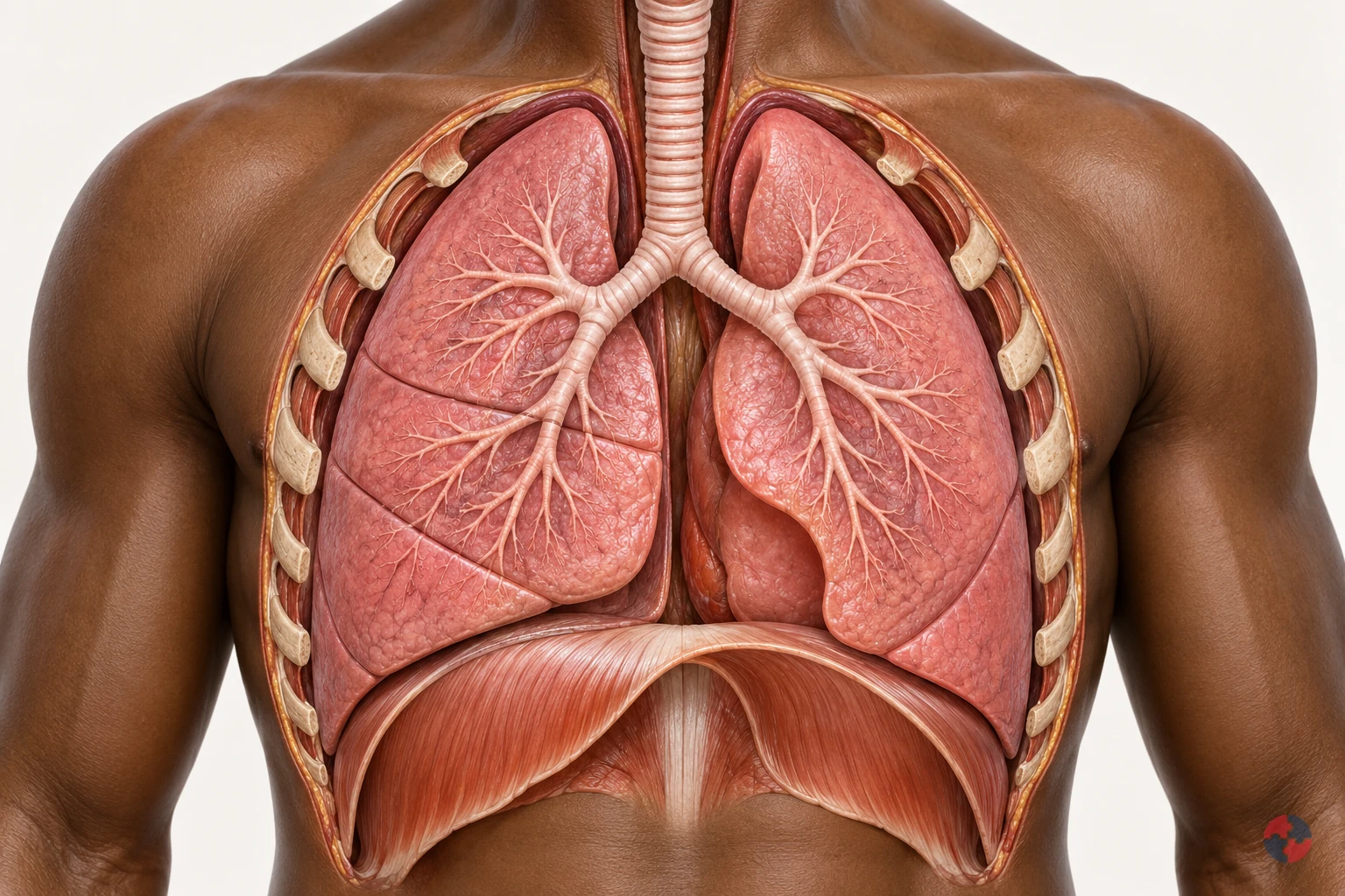 View full detail ↗